OPERATING AND INSTALLATION INSTRUCTIONS LG 250 A
PAGE 49
U
S
ER
G
ENER
A
L
S
P
EC
IA
LIS
T
P
ER
S
O
NNEL
Changes reserved
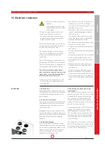
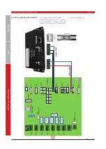
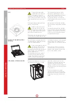
When connecting an external reheater
battery, the supply air temperature sensor
T4 installed in the ventilation unit must
be connected to input T5 (outdoor air
temperature).
The external supply air sensor (available
as an optional accessory), 5 m in length, is
connected to input T5 and installed in the
air duct after the heater battery. The user
must switch to the "Re-heater battery"
parameter in the operating software.
If a temperature sensor is not connected
to input T5, a fault message is output.
Where the reheater battery is controlled
using external temperature control, the
reheater battery parameter in the operat-
ing software must be set to "None".
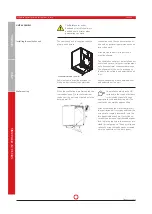
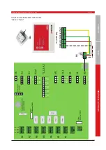
Connection for an electric reheater battery
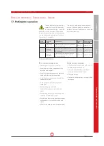
16. Maintenance and cleaning
Always pull the mains plug or
fully isolate the ventilation unit
from the mains when carrying
out cleaning or maintenance work on the
ventilation unit!
Other unit parts and components e.g. geo-
thermal heat exchanger, pre- and reheat-
er battery, sound absorbers etc. must be
serviced and cleaned in accordance with
the regulations and instructions. When
opening or unscrewing the front cover or
covers, always proceed with extreme care,
with due attention to safety and risks.
If possible, use a vacuum cleaner to
remove dirt and dust. Applying force or
using compressed air for cleaning may
damage components and surfaces.
Never use aggressive or solvent-contain-
ing cleaning agents.
The electrical components must not be
exposed to moisture or wet conditions.
The
Safety
information under
Section 4
- and in particular the
point on electrical
connections (Page 9) -
must be observed
when performing any electrical work.
SAFETY INSTRUCTIONS
Only specialists are allowed to
carry out the work specifi ed
below on the ventilation unit. Any
defects detected during servicing must
be remedied immediately to ensure safe
operation of the unit.
Only original spare parts may be used for
repairs and replacements.
MAINTENANCE INSTRUCTIONS FOR SPE-
CIALIST COMPANIES
Attention:
Bypass fl aps do not
move or drive manually.
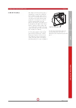
Annual cleaning is recommended at the
least, depending on the degree of soiling
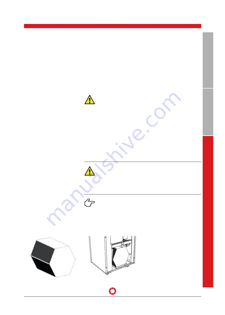
of the heat exchanger.
The heat exchanger must be carefully
removed from the unit for maintenance.
The heat exchanger can be cleaned by
rinsing with warm water (maximum
50 °C) and normal detergents, and fi nally
rinsing with warm water. Never blast the
exchanger with compressed air. This can
destroy the heat exchanger!
Before installing the exchanger in the
unit, the guide rails on the heat exchanger
must be greased lightly to ensure easy
and smooth insertion.
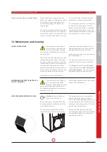
HEAT EXCHANGER WITH BYPASS FLAP
A
1
2
3
C
E
1
D
2
3
B
7
A
E
IN
B
A
U
V
O
R
S
C
H
L
A
G
C
4
4
5
6
7
E
D
5
6
B
Benennung:
Datum:
Gezeichnet:
Kunde:
Blatt Nr.
Dateiname:
Maßstab:
DIESER PLANUNGSVORSCHLAG IST NUR IN VERBINDUNG MIT UNSEREN VORBEMERKUNGEN GÜLTIG!
BEHÖRDENAUFLAGEN SIND BAUSEITIG ABZUKLÄREN UND UNBEDINGT EINZUHALTEN!
NATURMASZE UND HÖHENKOTEN SIND ZU ÜBERPRÜFEN!
UNSTIMMIGKEITEN SIND MIT DEM PLANVERFASSER ABZUKLÄREN!
ALLE MASZE SIND VOR DER AUSFÜHRUNG VOM KUNDEN ZU PRÜFEN!
Geprüft:
Diese Zeichnung stellt
nach
den Urh. Ges § 24 unser geistiges Eigentum
dar und darf ohne unsere ausdrückliche Zustimmung weder Konkurrenzfirmen,
noch dritten Personen weitergegeben werden. Die unbefugte bzw. bestimmungswidrige
Verwendung dieser Unterlagen ist nicht gestattet und wird gerichtlich verfolgt.
08LG250-A-L-V LG250 Baugruppe
Gerät L
Baugruppe.idw
23.01.2017
wroth
Prüfer:
1 von 1
1 : 50
Freimaßtoleranz nach DIN ISO 2768-mH
Zeichnungsstatus: Freigegeben
Revision:
-
Gespeichert: 02.02.2017 14:05:13
Bauvorhaben:
Gewicht:
62,444 kg
Auftragsnummer:
J. Pichler Gesellschaft m.b.H
9021 Klagenfurt, Karlweg 5, Postfach 32
T +43 (0)46332769, F +43 (0)463 37548
office@pichlerluft.at, www.pichlerluft.at
wroth
30.11.2016
Zeichnungsnummer:
Artikelnummer.
08LG250-A-L-V

