background image

SECTION 5 - CONNECTOR INFORMATION 

Page 5.1

pickering

GENERAL PURPOSE REED RELAY MODULE  50-110/115-021/121

SECTION 5 - CONNECTOR INFORMATION

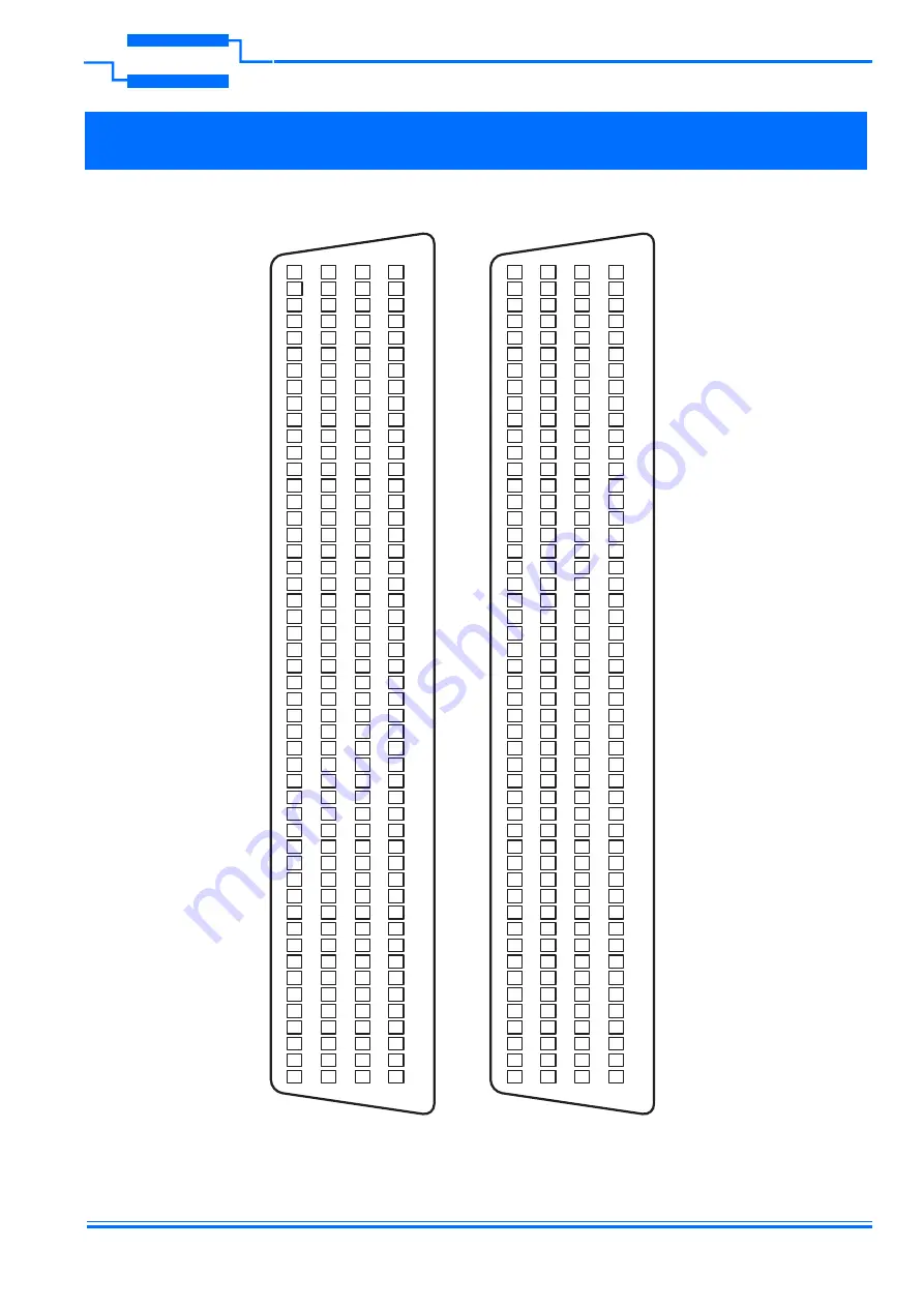
Figures 5.1 and 5.2 provide the Pin-Out information for the General Purpose Reed Relay Module.

151
152
153
154
155
156
157
158
159
160
161
162
163
164
165
166
167
168
169
170
171
172
173
174
175
176
177
178
179
180
181
182
183
184
185
186
187
188
189
190
191
192
193
194
195
196
197
198
199
200

150
149
148
147
146
145
144
143
142
141
140
139
138
137
136
135
134
133
132
131
130
129
128
127
126
125
124
123
122
121
120
119
118
117
116
115
114
113
112
111
110
109
108
107
106
105
104
103
102
101

51
52
53
54
55
56
57
58
59
60
61
62
63
64
65
66
67
68
69
70
71
72
73
74
75
76
77
78
79
80
81
82
83
84
85
86
87
88
89
90
91
92
93
94
95
96
97
98
99

100

50
49
48
47
46
45
44
43
42
41
40
39
38
37
36
35
34
33
32
31
30
29
28
27
26
25
24
23
22
21
20
19
18
17
16
15
14
13
12
11
10

9
8
7
6
5
4
3
2
1

A1
B1
C1
A5
B5
C5
A9
B9
C9
A13
B13
C13
A17
B17
C17
A21
B21
C21
A25
B25
C25
A29
B29
C29
A33
B33
C33
A37
B37
C37
A41
B41
C41
A45
B45
C45
A49
B49
C49
A53
B53
C53
A57
B57
C57
A61
B61
C61
-
Gnd

A2
B2
C2
A6
B6
C6
A10
B10
C10
A14
B14
C14
A18
B18
C18
A22
B22
C22
A26
B26
C26
A30
B30
C30
A34
B34
C34
A38
B38
C38
A42
B42
C42
A46
B46
C46
A50
B50
C50
A54
B54
C54
A58
B58
C58
A62
B62
C62
-
Gnd

A3
B3
C3
A7
B7
C7
A11
B11
C11
A15
B15
C15
A19
B19
C19
A23
B23
C23
A27
B27
C27
A31
B31
C31
A35
B35
C35
A39
B39
C39
A43
B43
C43
A47
B47
C47
A51
B51
C51
A55
B55
C55
A59
B59
C59
A63
B63
C63
-
Gnd

A4
B4
C4
A8
B8
C8
A12
B12
C12
A16
B16
C16
A20
B20
C20
A24
B24
C24
A28
B28
C28
A32
B32
C32
A36
B36
C36
A40
B40
C40
A44
B44
C44
A48
B48
C48
A52
B52
C52
A56
B56
C56
A60
B60
C60
A64
B64
C64
-
Gnd

151
152
153
154
155
156
157
158
159
160
161
162
163
164
165
166
167
168
169
170
171
172
173
174
175
176
177
178
179
180
181
182
183
184
185
186
187
188
189
190
191
192
193
194
195
196
197
198
199
200

150
149
148
147
146
145
144
143
142
141
140
139
138
137
136
135
134
133
132
131
130
129
128
127
126
125
124
123
122
121
120
119
118
117
116
115
114
113
112
111
110
109
108
107
106
105
104
103
102
101

51
52
53
54
55
56
57
58
59
60
61
62
63
64
65
66
67
68
69
70
71
72
73
74
75
76
77
78
79
80
81
82
83
84
85
86
87
88
89
90
91
92
93
94
95
96
97
98
99

100

50
49
48
47
46
45
44
43
42
41
40
39
38
37
36
35
34
33
32
31
30
29
28
27
26
25
24
23
22
21
20
19
18
17
16
15
14
13
12
11
10

9
8
7
6
5
4
3
2
1

A1
B1
C1
A5
B5
C5
A9
B9
C9
A13
B13
C13
A17
B17
C17
A21
B21
C21
A25
B25
C25
A29
B29
C29
-
-
-
-
-
-
-
-
-
-
-
-
-
-
-
-
-
-
-
-
-
-
-
-
-
Gnd

A2
B2
C2
A6
B6
C6
A10
B10
C10
A14
B14
C14
A18
B18
C18
A22
B22
C22
A26
B26
C26
A30
B30
C30
-
-
-
-
-
-
-
-
-
-
-
-
-
-
-
-
-
-
-
-
-
-
-
-
-
Gnd

A3
B3
C3
A7
B7
C7
A11
B11
C11
A15
B15
C15
A19
B19
C19
A23
B23
C23
A27
B27
C27
A31
B31
C31
-
-
-
-
-
-
-
-
-
-
-
-
-
-
-
-
-
-
-
-
-
-
-
-
-
Gnd

A4
B4
C4
A8
B8
C8
A12
B12
C12
A16
B16
C16
A20
B20
C20
A24
B24
C24
A28
B28
C28
A32
B32
C32
-
-
-
-
-
-
-
-
-
-
-
-
-
-
-
-
-
-
-
-
-
-
-
-
-
Gnd

50-110-021

50-110-121

Figure 5.1 - General Purpose Reed Relay Module (50-110-021/121): Pin-Outs

Artisan Technology Group - Quality Instrumentation ... Guaranteed | (888) 88-SOURCE | www.artisantg.com

Summary of Contents for PCI CONVENTIONAL 50-110-021

Page 1: ...service in house repair center WE BUY USED EQUIPMENT Sell your excess underutilized and idle used equipment We also offer credit for buy backs and trade ins www artisantg com WeBuyEquipment REMOTE IN...
Page 2: ...115 021 121 USER MANUAL GENERAL PURPOSE REED RELAY MODULE MODEL Nos 50 110 115 021 121 www pickeringtest com pickering ISO 9002 Reg No FM38792 Issue 4 0 April 2012 Artisan Technology Group Quality In...

Page 3: ...s publication may be reproduced transmitted transcribed translated or stored in any form or by any means without the written permission of Pickering Interfaces Technical details contained within this...

Page 4: ...ycled or disposed of in a safe and environmentally friendly manner Worldwide Technical Support and Product Information http www pickeringtest com Pickering Interfaces Headquarters Stephenson Road Clac...

Page 5: ...Page iv pickering GENERAL PURPOSE REED RELAY MODULE 50 110 115 021 121 THIS PAGE INTENTIONALLY BLANK Artisan Technology Group Quality Instrumentation Guaranteed 888 88 SOURCE www artisantg com...

Page 6: ...tion 3 1 Software Installation 3 2 Section 4 Programming Guide 4 1 Programming Options For Pickering PCI Cards 4 1 Module Architecture 4 2 Module Sub Units 4 3 Programming The Module 4 5 Section 5 Con...

Page 7: ...Page vi pickering GENERAL PURPOSE REED RELAY MODULE 50 110 115 021 121 THIS PAGE INTENTIONALLY BLANK Artisan Technology Group Quality Instrumentation Guaranteed 888 88 SOURCE www artisantg com...

Page 8: ...lays used in our PCI cards are manufactured by our sister company Pickering Electronics Pickering reed relays offer very high reliability over 108 operations with maximum switching performance especia...

Page 9: ...agrams for the 50 110 115 120 125 Reed Relay Card Operating Storage Conditions Operating Conditions Operating Temperature Humidity Altitude 0 C to 55 C Up to 90 non condensing 5000m Storage and Transp...

Page 10: ...relays depending on the module type The relays are energised via control signals from relay drivers U8 to U15 The relay driver is addressed by PCI bridge U1 to output the required signal Module confi...

Page 11: ...ION 2 TECHNICAL DESCRIPTION pickering GENERAL PURPOSE REED RELAY MODULE 50 110 115 021 121 THIS PAGE INTENTIONALLY BLANK Artisan Technology Group Quality Instrumentation Guaranteed 888 88 SOURCE www a...

Page 12: ...nded 2 Choose an appropriate free PCI slot in the host system 3 Remove the blanking plate for the chosen slot and retain the fixing screw 4 Carefully remove the card from its anti static bag and inser...

Page 13: ...ortcut on the Programs Pickering menu In the absence of LabVIEW the Runtime Engine is required to support the Pickering Test Panels application TESTING OPERATION After installation of the hardware sta...

Page 14: ...VI Interchangeable Virtual Instrument driver supports all Pickering Interfaces PXI switch cards that are consistent with the Iviswtch class model as are the great majority of cards in the System 40 45...

Page 15: ...Pickering card are organized into logical sub units each sub unit containing a set of objects of similar type and use These objects may be switches digital outputs digital inputs resistors power supp...

Page 16: ...2 A32 C32 B1 A1 C1 B2 A2 C2 A64 C64 A1 C1 A2 C2 A3 C3 50 110 121 64 x SPDT 50 115 021 32 x SPST 50 115 121 64 x SPST Sub Unit Bit Signal Path Relay Energised 50 110 021 50 115 021 Signal Path Relay En...

Page 17: ...31 A31 com31 A31 31 32 com32 A32 com32 A32 32 33 com33 A33 33 34 com34 A34 34 35 com35 A35 35 36 com36 A36 36 37 com37 A37 37 38 com38 A38 38 39 com39 A39 39 40 com40 A40 40 41 com41 A41 41 42 com42 A...

Page 18: ...iUInt32 values are needed to hold the entire pattern ViUInt32 data 2 data 0 1 Sets lowest bit to 1 chA1 to com1 pipx40_setChannelPattern vi sub_unit data data 0 0x20 Sets 6th bit chA6 to com6 All othe...

Page 19: ...CTION 4 PROGRAMMING GUIDE pickering GENERAL PURPOSE REED RELAY MODULE 50 110 115 021 121 THIS PAGE INTENTIONALLY BLANK Artisan Technology Group Quality Instrumentation Guaranteed 888 88 SOURCE www art...

Page 20: ...3 A27 B27 C27 A31 B31 C31 A35 B35 C35 A39 B39 C39 A43 B43 C43 A47 B47 C47 A51 B51 C51 A55 B55 C55 A59 B59 C59 A63 B63 C63 Gnd A4 B4 C4 A8 B8 C8 A12 B12 C12 A16 B16 C16 A20 B20 C20 A24 B24 C24 A28 B28...

Page 21: ...A39 C39 A43 C43 A47 C47 A51 C51 A55 C55 A59 C59 A63 C63 Gnd A4 C4 A8 C8 A12 C12 A16 C16 A20 C20 A24 C24 A28 C28 A32 C32 A36 C36 A40 C40 A44 C44 A48 C48 A52 C52 A56 C56 A60 C60 A64 C64 Gnd 151 152 153...

Page 22: ...configuration highlighting any potential configuration problems Specific details of all installed Pickering switch cards are included All the installed Pickering switch cards should be listed in the...

Page 23: ...TROUBLE SHOOTING pickering GENERAL PURPOSE REED RELAY MODULE 50 110 115 021 121 Page 6 2 THIS PAGE INTENTIONALLY BLANK Artisan Technology Group Quality Instrumentation Guaranteed 888 88 SOURCE www art...

Page 24: ...unction with the PCB layout diagram below to identify the position of faulty relays Figure 7 1 Modules 50 110 021 50 115 021 Component Layout RL1 U1 FX1 U14 U13 U12 U11 FX2 U10 U9 U8 C24 C23 C25 C26 C...

Page 25: ...9 RL20 RL21 RL22 RL23 RL24 RL25 RL26 RL27 RL28 RL29 RL30 RL31 RL32 RL33 RL34 RL35 RL36 RL37 RL38 RL39 RL40 RL41 RL42 RL43 RL44 RL45 RL46 RL47 RL48 RL49 RL51 RL53 RL55 RL57 RL59 RL61 RL63 RL50 RL52 RL5...

Page 26: ...ain semiconductor devices used in this equipment are liable to damage due to static voltage Observe the following precautions when handling these devices in their unterminated state or sub units conta...

Page 27: ...Page 8 2 pickering GENERAL PURPOSE REED RELAY MODULE 50 110 115 021 121 THIS PAGE INTENTIONALLY BLANK Artisan Technology Group Quality Instrumentation Guaranteed 888 88 SOURCE www artisantg com...

Page 28: ...service in house repair center WE BUY USED EQUIPMENT Sell your excess underutilized and idle used equipment We also offer credit for buy backs and trade ins www artisantg com WeBuyEquipment REMOTE IN...

Reviews: