Page 2.2
POWER RELAY MODULE 40-160
pickering
SECTION 2 - TECHNICAL DESCRIPTION
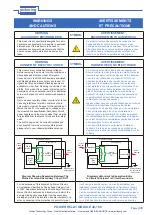
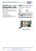
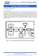
Figure 2.2 - Power Relay Module 40-160-003: Functional Block Diagram
40-160-003
A functional block diagram is provided in Figure 2.2. The Power Relay Module 40-160-003 is powered by +12V and
+5V inputs via Compact PCI connector J1. The interface to the user test equipment is via two front panel mounted
20-pin GMCT type connectors. The module comprises a PCB which provides mounting for control logic and twenty
12V relays RL1 to RL20. Relays RL1 to RL5 and RL9 and RL10 are energised via control signals from relay driver
U10. Relays RL6 to RL8 and RL11 to RL20 are energised via control signals from relay driver U11. The relay drivers
are addressed by PCI bridge U1 to output the required signal. PCI Bridge U1 is configured by EEPROM U2.
Relays RL1-20
20xSPST
2x Front Panel Male 20-pin GMCT
Connectors
Control Logic
U3-6
& Module
Configuration
U7
PCI Bridge
Configuration
U2
Terminating
Resistors
R1-12
PCI Bridge U1
Compact PCI Bus Connector J1
PXI POWER RELAY MODULE 40-160-003
GND
Relay
Drivers
U10-11
+5V
+12V
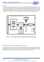
MAXIMUM FREQUENCY OF OPERATIONS AT FULL LOAD
At full load breaking contacts can create a significant amount thermal load inside the relays by the generation of
strong signal arcs. If the relays are operated near full load then the rate of operations (a complete on and off cycle)
should be limited to a repetition rate of 0.3Hz to avoid the resulting heat damaging the relay plastic components.
Repeated operation at closer time intervals under full load will result in premature relay failure.
Artisan Technology Group - Quality Instrumentation ... Guaranteed | (888) 88-SOURCE | www.artisantg.com

