background image

Page (VII)

POWER RELAY MODULE 40-160

pickering

Page (VII)

GENERAL PURPOSE 2A RELAY MODULE 40-131/132

pickering

!

WARNINGS 

AND CAUTIONS

AVERTISSEMENTS 

ET PRÉCAUTIONS

WARNING 

HAZARDOUS ENVIRONMENTS

SYMBOL

AVERTISSEMENT 

ENVIRONNEMENTS DANGEREUX

This product is not specifically designed for use in 

hazardous environments, for example in explosive 

atmospheres. If the product is to be used in 

hazardous environments we recommend that the 

user ensures suitable protective measures are 

taken.

Ce produit n’est spécifiquement pas conçu pour un 

usage dans des environnements dangereux, par 

exemple en atmosphères explosives. Si le produit doit 

être utilisé dans des environnements dangereux, nous 

recommandons à l’utilisateur de s’assurer que des 

mesures de protection appropriées soient prises.

WARNING 

DANGER OF ELECTRIC SHOCK

SYMBOL

AVERTISSEMENT 

DANGER DE CHOC ELECTRIQUE

This module may contain hazardous voltages. 

Before removing the module from the rack remove 

all supplies and disconnect user I/O signals.
Unused slots in the PXI/LXI chassis are populated 

with blanking plates to prevent access to user I/O 

signals that may be present. Blanking panels are 

available to order from Pickering in a variety of slot 

widths. If the product is not used in this manner for 

example by using an extender card then additional 

care must be taken to avoid contact with exposed 

signals.
Not to be used in safety critical circuits, refer to the 

Pickering Interfaces’ terms & conditions of sale.
This module must not be used for the switching of 

Mains Circuits. For the switching of voltages up to 

the module’s full specification, Secondary Circuit 

power supplies and the Device Under Test must be 

fully isolated from the Mains Circuit and the safety 

earth.
The host chassis must be correctly installed and 

be connected to mains or factory safety ground, 

please refer to your chassis installation manual.

Ce module peut contenir des tensions dangereuses. 

Avant de retirer le module de la baie, enlever toutes les 

fournitures et déconnecter les signaux d’E/S utilisateur.
Les slots non utilisés dans le châssis PXI/LXI sont 

peuplées d’obturateurs pour empêcher l’accès aux 

signaux d’E/S utilisateur qui peuvent être présents. 

Les obturateurs sont disponibles sur commande chez 

Pickering dans une variété de largeur de fente. Si le 

produit est utilisé sans obturateur, par exemple en 

utilisant une carte d’extension, alors des précautions 

supplémentaires doivent être prises pour éviter tout 

contact avec les signaux exposés.
Ne pas utiliser dans des circuits critiques de sécurité, se 

référer à nos Conditions Générales de Ventes.
Ce module ne doit pas être utilisé pour la commutation 

des circuits principaux. Pour la commutation de 

tensions jusqu’à la spécification complète du module, 

les alimentations des circuits secondaires et l’appareil 

sous test doivent être complètement isolés des circuits 

principaux et de la terre de sécurité.
Le châssis hôte doit être correctement installé et 

connecté à la terre ou au réseau de sécurité d’usine. 

Veuillez-vous reporter au manuel d’installation de votre 

châssis.

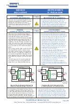
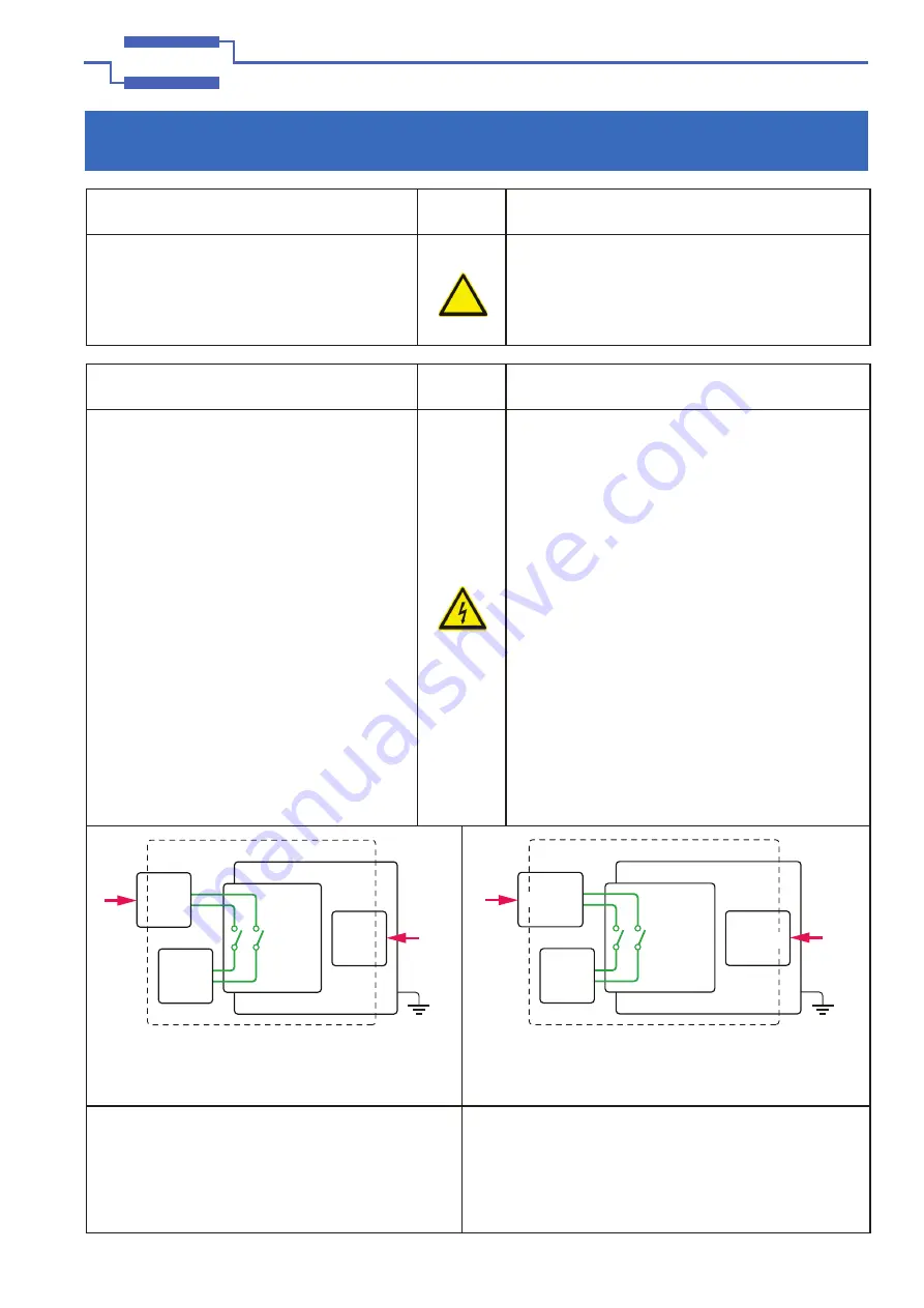
Diagram Showing Separation Between The 

Mains Circuit and Secondary Circuit / DUT

Diagramme Montrant la Séparation Entre 

le Circuit Principal et le Circuit Secondaire

For the purposes of this document, a Mains Circuit is 

an installation classified as Overvoltage Category II up 

to 300V. Separation between the Secondary Circuit and 

Mains Circuit is achieved by a transformer in which the 

primary windings are separated from the secondary 

windings by reinforced insulation, double insulation, or a 

screen connected to the protective conductor terminal.

Aux fins du présent document, un circuit principal est une 

installation classée dans la Catégorie de Surtension Groupe 

II jusqu’à 300V. la séparation entre le circuit secondaire et le 

circuit principal est réalisée par un transformateur dans lequel 

les enroulements primaires sont séparés des enroulements 

secondaires par une isolation renforcée, une double isolation 

ou un blindage relié à la borne de conducteur de protection.

PXI

Switching

Module

Device

Under

Test

Host Chassis

Secondary  Circuit

Mains 

Circuit

Mains

Circuit

Power

Supply

Power

Supply

Mains/Factory 

safety ground

Module

Commutation

PXI

Appareil

Sous

Test

Châssis Hôte

Circuit Secondaire

Circuit

Principal

Circuit

Principal

Alimentation

Alimentation

Secteur/Réseau

de sécurité au

sol de l’usine

Artisan Technology Group - Quality Instrumentation ... Guaranteed | (888) 88-SOURCE | www.artisantg.com

Summary of Contents for PXI 40-160 Series

Page 1: ...service in house repair center WE BUY USED EQUIPMENT Sell your excess underutilized and idle used equipment We also offer credit for buy backs and trade ins www artisantg com WeBuyEquipment REMOTE IN...

Page 2: ...Y MODULE 40 160 pickering Issue 3 5 February 2018 User Manual Power Relay Module Model No 40 160 pickeringtest com pickering Artisan Technology Group Quality Instrumentation Guaranteed 888 88 SOURCE w...

Page 3: ...his publication may be reproduced transmitted transcribed translated or stored in any form or by any means without the written permission of Pickering Interfaces Technical details contained within thi...

Page 4: ...relevant environmental laws and regulations and reduce wastes and releases to the environment Pickering Interfaces aims to design and operate products in a way that protects the environment and the h...

Page 5: ...AVERTISSEMENT ATTENTION Des consignes de s curit appropri es doivent tre suivies En cas de danger potentiel existant prendre des pr cautions Consulter les instructions d taill es dans le manuel du pro...

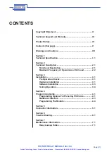
Page 6: ...Full Load 2 2 Section 3 Installation 3 1 Pre Operation Checks 3 1 Hardware Installation 3 1 Software Installation 3 3 Testing Operation 3 4 Section 4 Programming Guide 4 1 Programming Options For Pic...

Page 7: ...Page VI POWER RELAY MODULE 40 160 pickering THIS PAGE INTENTIONALLY BLANK Artisan Technology Group Quality Instrumentation Guaranteed 888 88 SOURCE www artisantg com...

Page 8: ...r l acc s aux signaux d E S utilisateur qui peuvent tre pr sents Les obturateurs sont disponibles sur commande chez Pickering dans une vari t de largeur de fente Si le produit est utilis sans obturate...

Page 9: ...ntrepos es et transport es dans des sacs antistatiques CAUTION PRODUCT DOCUMENTATION SYMBOL ATTENTION DOCUMENTATION PRODUIT Suitably qualified trained users should ensure that the accompanying documen...

Page 10: ...ications requiring switching of either mains voltage or DC current The 40 160 module has a choice of SPST relays capable of switching 10A at 250VAC or DPST relays capable of switching 8A at 250VAC All...

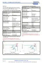
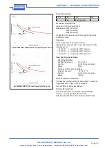
Page 11: ...relays gold flash over silver alloy A Spare Relay is built onto the circuit board to facilitate easy maintenance with minimum downtime AC Resistive AC Inductive DC Resistive DC Inductive 40 160 001 0...

Page 12: ...and meet applicable EU directives Low voltage safety EN61010 1 2001 EMC Immunity EN61000 6 1 2001 Emissions EN55011 1998 Mechanical Characteristics Single slot 3U PXI CompactPCI card Module weight 24...

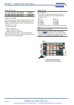
Page 13: ...iven a unique part number fully documented and may be ordered at any time in the future Please contact your local sales office to discuss Side View of 40 160 003 20 x SPST Power Relay Module Support P...

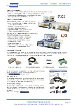
Page 14: ...chassis Pickering Interfaces LXI or LXI USB Modular Chassis Chassis Selection Guide Standard PXI or hybrid PXIe Chassis from any Vendor Mix our 1000 PXI switching simulation modules with any vendor s...

Page 15: ...product and support videos articles as well as complete product catalogs and product reference maps to assist when looking for the switching simulation and cable and connector solutions you need We ha...

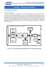
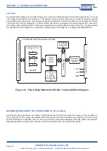
Page 16: ...r U13 Relays RL2 and RL6 are energised via control signals from relay driver U12 Relay drivers U12 and U13 are interfaced to the low power digital control logic via sink drivers U9 and U10 respectivel...

Page 17: ...e U1 to output the required signal PCI Bridge U1 is configured by EEPROM U2 Relays RL1 20 20xSPST 2x Front Panel Male 20 pin GMCT Connectors Control Logic U3 6 Module Configuration U7 PCI Bridge Confi...

Page 18: ...erfaces N essayez pas d installer le mat riel si des d g ts sont vidents 2 Placez le ch ssis contenant le module par rapport tout autre quipement qui est cens se connecter avec Assurez vous que le ch...

Page 19: ...s no requirement to use any particular power up sequence Le module doit tre install conform ment la proc dure suivante 1 Assurez vous que le syst me est teint mais qu il reste connect au r seau lectri...

Page 20: ...to support the Pickering Test Panels application D abord installez les pilotes de la carte de commutation PXI de Pickering en ex cutant le programme d installation Setup exe fourni dans un fichier com...

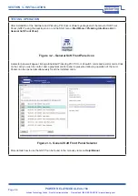
Page 21: ...t menu Start Menu Pickering Interfaces Ltd General Soft Front Panel A selector panel will appear listing all installed Pickering PCI PXI or LXI switch cards and resistor cards Click on the card you wi...

Page 22: ...and Pilpxi documents are included in the Pipx40vpp software installation IVI Driver for Windows pi40iv The pi40iv IVI Interchangeable Virtual Instrument driver supports all Pickering Interfaces PXI sw...

Page 23: ...ve driver is also available Once again this may be used for both LXI and PXI card control SOAP Pickering LXI products include a SOAP interface which is usable from a wide variety of platforms and lang...

Page 24: ...1 A1 2 to C1 2 A1 to C1 1 2 A2 to C2 A2 1 to C2 1 A2 2 to C2 2 A2 to C2 1 3 A3 to C3 A3 1 to C3 1 A3 2 to C3 2 A3 to C3 1 4 A4 to C4 A4 1 to C4 1 A4 2 to C4 2 A4 to C4 1 5 A5 to C5 A5 1 to C5 1 A5 2 t...

Page 25: ...tes the A1 C1 relay pipx40_setChannelState vi sub_unit 1 VI_OFF Releases the A1 C1 relay pipx40_setChannelState vi sub_unit 6 VI_ON Operates the A6 C6 relay setChannelPattern Sub unit is 10 bits wide...

Page 26: ...igure 5 2 10 x DPST Power Relay Module 40 160 002 Pinouts 20 pin male GMCT connectors viewed from the front of the module A D H L P T W B E J M R U C F K N S V X A1 1 C1 1 A1 2 C1 2 A2 1 C2 1 A2 2 C2...

Page 27: ...the front of the module A D H L P T W B E J M R U C F K N S V X A1 C1 A2 C2 A3 C3 A4 C4 A5 C5 A6 C6 A7 C7 A8 C8 A9 C9 A10 C10 A D H L P T W B E J M R U C F K N S V X A11 C11 A12 C12 A13 C13 A14 C14 A...

Page 28: ...me est sous tension et pendant le d marrage de Windows vous devriez vous attendre voir l activit p riodique sur l interface de commande distance RX TX indicateur jaune de compensation pour ne laisser...

Page 29: ...rds if they are currently opened by some other application such as the Test Panels or Terminal Monitor Dans la section Informations VISA si VISA n est pas install cette absence sera signal e Cela n af...

Page 30: ...ire Si le module a t introduit apr s que le ch ssis LXI ait t fabriqu le module peut ne pas tre reconnu dans ce cas le firmware du ch ssis peut avoir besoin d une mise niveau C est un processus simple...

Page 31: ...A4 2 to C4 2 A4 to C4 RL4 A5 to C5 A5 1 to C5 1 A5 2 to C5 2 A5 to C5 RL5 A6 to C6 A6 1 to C6 1 A6 2 to C6 2 A6 to C6 RL6 A7 to C7 A7 1 to C7 1 A7 2 to C7 2 A7 to C7 RL7 A8 to C8 A8 1 to C8 1 A8 2 to...

Page 32: ...C13 C14 C15 C16 C17 C18 C19 C20 C21 C22 C23 C24 C25 R2 C28 R1 C29 C31 C26 C32 C27 C30 R3 R16 R17 R18 Q1 RL1 RL2 RL3 RL4 RL5 RL6 RL7 RL8 RL9 RL10 SPARE RELAY LK1 LK4 LK2 LK5 LK3 LK6 RL1 RL2 RL3 RL4 RL5...

Page 33: ...E 40 160 pickering SECTION 7 MAINTENANCE INFORMATION Figure 7 3 Power Relay Module 40 160 001 Figure 7 4 Power Relay Module 40 160 003 Artisan Technology Group Quality Instrumentation Guaranteed 888 8...

Page 34: ...service in house repair center WE BUY USED EQUIPMENT Sell your excess underutilized and idle used equipment We also offer credit for buy backs and trade ins www artisantg com WeBuyEquipment REMOTE IN...

Reviews: