6
CONTACT US TOLL FREE
800-421-6511
www.
picomacom
.com
PICO MACOM
Owners Manual
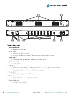
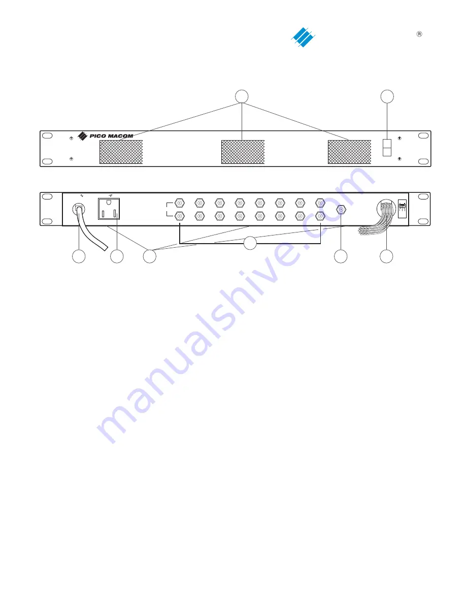
Front Pannel
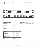
1. Blower exhaust port:
• Cooling air exits these ports.
2. Power switch:
• Switch activates the power supply.
• The plug is considered the disconnect device and should “remain readily accessible”.
3. Power cord:
• Plug this three wire, standard U.S.A. type into a 90 - 265Vac outlet.
4. Convenience outlet:
• 117Vac, 600W
5. Input ports:
• Connect RF output to these ports. Adjacent ports, 1 to 3 to 5 etc. have 38dB minimum isolation.
Opposite ports 1 to 2, 3 to 4 etc. have 55dB minimum isolation.
6. Output port:
• Combined output signal present at this port.
7. Power cables:
• Connect each of these 3 pin cables to the modules.
8. Blower intake port:
• Cooling air enters these ports.
OUTPUT
INPUTS
1
2
3
4
5
6
7
8
9
10
11
12
13
14
15
16
MPC-16PS/CS
Power Supply and Combiner/Cooling System
®
OFF
RESET
1
2
3
4
6
7
8
5
120Vac 60Hz 5A 600W MAX
DC 5V 0.28
A
DC 12V 0.28
A
GN
D
Class 2
wiring
120 Vac 60Hz
800W


