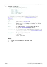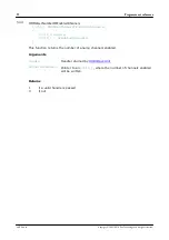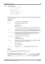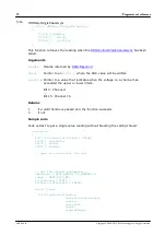
12
ADC-20/ADC-24 User's Guide
5
Programmer's reference
5.1
Recording methods
The ADC-20/ADC-24
provides three methods of recording data. All these
methods support
The driver constantly polls the device, and samples are placed in a buffer until
retrieved by your application. Precise sample timing is controlled by the unit.
You make a single request for a sample, blocking the calling thread, and when the
sample has been received the driver returns the value to your application.
You make a single request for a sample without blocking the calling thread, and
when the sample has been received the driver returns the value to your
application.
5.2
Windows driver
The
picohrdl.dll
in the
lib
subdirectory of your SDK
installation is a driver that allows you to program your ADC-20 or ADC-24
.
It is supplied in 32-bit and 64-bit versions. The driver exports the
in standard C format, but this does not limit you to programming in C. You can use the
API with any programming language that supports standard C calls. It can also be
used with programs like Microsoft Excel. The driver supports all Windows operating
systems from Windows 7 onwards.
5.3
Scaling
To convert from ADC values to volts, first obtain the minimum and maximum ADC
values for the selected channel by calling the
function in
the driver. Next, scale the ADC value to the voltage range you specified when you
called
. You can calculate the voltage range
programmatically by using
Vmax = 2500 mV / (2^r)
where
r
is the range constant you supplied to
(0 for
±2500 mV, 1 for ±1250 mV and so on).
You can then use Vmax to calculate the scaled voltage, V, with the following formula
V = (raw_ADC_value / max_ADC_Value) * Vmax
where raw_ADC_value is the reading from the device and max_ADC_value is the max
ADC value for the device obtained from
Copyright © 2005–2016 Pico Technology Ltd. All rights reserved.
adc20.en r6


