background image

Product information

8

Copyright © 2013 Pico Technology Ltd. All rights reserved.

usbpt104.en r2

Power-saving tip

If you wish to stop using the PT-104 Data Logger in Ethernet mode, you
can use the 

Ethernet Settings 

utility to disable its Ethernet port. This

reduces the power consumption of the device when used in USB mode.

Ethernet and USB

Do not use the PT-104 Data Logger in USB mode when it is being powered
by Power-over-Ethernet (PoE). This could cause the unit to radiate
electromagnetic energy outside the limits permitted by FCC and EU
regulations, and could also cause it to produce spurious measurements. It
will not, however, cause permanent damage to the unit.

LAN connection

To use the PT-104 Data Logger on a local-area network (LAN), connect it to your
network switch or network router using the Ethernet cable provided.

Direct connection

You can also connect the PT-104 Data Logger directly to the network port on your
computer. For this connection, you will need to use an Ethernet crossover cable (not
supplied).

Power over Ethernet (PoE)

The PT-104 Data Logger can obtain its power from the Ethernet port as a Powered
Device (PD) according to the PoE standard. To use this feature, you must connect the
unit to Power Sourcing Equipment (PSE) such as a network switch, router or power
injector that also supports the PoE standard. Any standard Ethernet cable up to 100 m
(about 328 ft) in length can be used.

Summary of Contents for PT-104

Page 1: ...Copyright 2013 Pico Technology Ltd All rights reserved PT 104 Data Logger User s Guide usbpt104 en r2 ...

Page 2: ......

Page 3: ...1 Overview 2 2 Safety warnings 3 3 Legal information 4 2 Product information 4 1 Pack contents 5 2 Specifications 6 3 Installing the driver 6 4 Connection USB port 7 5 Connection Ethernet port 9 6 Connection PRT inputs 10 7 Setting up 12 8 The back panel 13 3 Background information 13 1 Platinum resistance thermometers PRTs 15 Index ...

Page 4: ......

Page 5: ... PT100 PT1000 and resistance modes the unit can use a two three or four wire circuit Four wire measurement gives the greatest accuracy In voltage mode the input connector can be treated as a differential input with ground or as two single ended inputs Programmer s Guide All the software that you need for everyday use of the PT 104 Data Logger is supplied with the unit For more advanced application...

Page 6: ...re when measuring temperatures near mains line powered equipment If in doubt use a meter to check that there is no hazardous AC or DC voltage on the equipment If a sensor is accidentally connected to a mains voltage you risk damage to the converter and your computer and your computer chassis may become live resulting in injury to yourself and others DO NOT exceed the maximum input voltage range of...

Page 7: ...o Technology cannot guarantee that its equipment or software is suitable for a given application It is your responsibility therefore to ensure that the product is suitable for your application Mission critical applications This software is intended for use on a computer that may be running other software products For this reason one of the conditions of the license is that it excludes usage in mis...

Page 8: ... 2 Product information 2 1 Pack contents Please check that your PT 104 pack order code PP682 contains the following items Quantity Reorder code Description 1 PP682 PT 104 Data Logger 1 DO112 USB Installation Guide 1 MI106 USB lead 1 DI025 Software and Reference CD 1 TA076 Ethernet patch cable ...

Page 9: ...nce 1 M Overvoltage protection 30 V Output USB or Ethernet Power Powered by USB or Ethernet USB 1 1 5 V 10 100 mA USB 2 0 5 V 10 200 mA Ethernet 48 V 20 40 mA 2 W Temperature range 20 C to 30 C for stated accuracy 0 C to 70 C operating 20 to 80 C storage Humidity range 20 to 90 RH non condensing operating 5 to 95 RH non condensing storage Dimensions W 135 x L 184 x H 36 mm 5 31 x 7 24 x 1 42 in So...

Page 10: ...ernatively you can download the driver from our website at http www picotech com 2 4 Connection USB port To use the PT 104 Data Logger connect its USB port to a USB port on your computer using the cable provided The first time you connect the device Windows will install the driver and then tell you that the device is ready for use You can then run the PicoLog software to start making measurements ...

Page 11: ...n the Pico Technology program group under the Windows Start menu 3 Set the Device Types control to PT 104 USB 4 The serial number of your device should appear in the device list Click the device once to select it 5 Set the Enable Ethernet Settings check box 6 Enter the IP address and port that you wish to give the device You may need to ask your network manager for an IP address that does not conf...

Page 12: ...surements It will not however cause permanent damage to the unit LAN connection To use the PT 104 Data Logger on a local area network LAN connect it to your network switch or network router using the Ethernet cable provided Direct connection You can also connect the PT 104 Data Logger directly to the network port on your computer For this connection you will need to use an Ethernet crossover cable...

Page 13: ...mber of channels from 4 to 8 It is supported by the driver so you can use it in your own applications It is not however supported by the PicoLog software Connector Channel Pin 1 1 3 5 2 2 2 3 6 2 3 3 3 7 2 4 4 3 8 2 Note on Differential Voltage Mode The maximum input voltage range of the PT 104 Data Logger is 2 5 V Any voltage in excess of 30 V on any input pin may cause permanent damage to the un...

Page 14: ...e File menu in the PicoLog software Recorder select New settings The Recording dialog box appears 2 Click OK The Sampling Rate dialog box appears 3 Click OK The Converter details dialog box appears 4 From the Converter type drop down list select either PT 104 USB or PT 104 Ethernet The dialog box will then show the converter list as in the following examples ...

Page 15: ...e with the correct type and IP address and click OK If your device does not appear in the list type its IP address and port number in the boxes below the list When you click OK the PT 104 Data Logger channels window will appear 6 In the PT 104 Data Logger channels window double click on Ch1 unused The Edit PT 104 Data Logger Channel dialog box appears 7 Type in a name for the channel if required 8...

Page 16: ... Data Logger should appear in the monitor window 2 8 The back panel A Ethernet port B USB port C Ethernet Data indicator Flashes to indicate Ethernet data transfer D Ethernet Link indicator On when Ethernet port connected to an active device E Power Status indicator On when power is applied Flashes to indicate conversion in progress ...

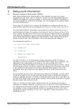
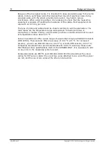
Page 17: ... x 10 3 B 5 775 x 10 7 C below 0 C 4 183 x 10 12 above 0 C 0 For a PT100 sensor a 1 C temperature change will cause a 0 384 change in resistance so even a small error in measurement of the resistance for example the resistance of the wires leading to the sensor can cause a large error in the measurement of the temperature For precision work sensors have four wires two to carry the sense current an...

Page 18: ... temperature range and exposure to fluids corrosive or conductive or metals Clearly normal solder junctions on cables should not be used at temperatures above about 170 C Sensor manufacturers offer a wide range of sensors that comply with BS1904 class B DIN 43760 These sensors offer an accuracy of 0 3 C at 0 C For increased accuracy you can use BS1904 class A 0 15 C or tenth DIN sensors 0 03 C Com...

Page 19: ...s impedance 5 number of 5 Installation 6 L LAN connection 7 Legal information 3 Liability 3 Linearity 5 M Mains voltages 2 Maximum input range 2 Mission critical applications 3 N Noise RMS 5 O Output 5 Overview 1 Overvoltage protection 5 P Pack contents 4 Power indicator 12 Power over Ethernet PoE 7 PRT background information 13 connection 9 R Range 5 Repairs 2 Resolution 5 S Safety warnings 2 Sen...

Page 20: ...Index 16 Copyright 2013 Pico Technology Ltd All rights reserved usbpt104 en r2 V Viruses 3 ...

Page 21: ...PT 104 Data Logger User s Guide 17 Copyright 2013 Pico Technology Ltd All rights reserved usbpt104 en r2 ...

Page 22: ...es House Colmworth Business Park ST NEOTS Cambridgeshire PE19 8YP United Kingdom Tel 44 0 1480 396 395 Fax 44 0 1480 396 296 www picotech com Copyright 2013 Pico Technology Ltd All rights reserved usbpt104 en r2 26 06 13 ...

Reviews: