Product information
16
Copyright © 2013 Pico Technology Ltd. All rights reserved.
usbdrdaq.en r4
2.9.4
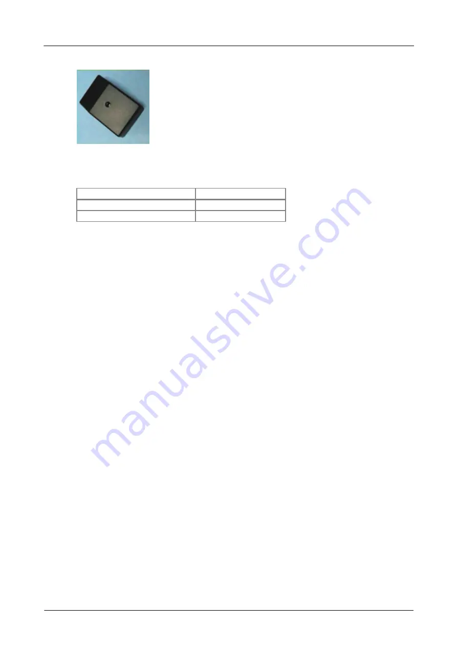
PP066 Reed Switch
A reed switch sensor can be used to detect the presence of a magnetic field such as
that from a bar magnet or an electromagnet. Alternatively, a simple single-pole switch
can be connected to terminals inside the unit.
Size
72 x 45 x 28 mm
Operating range
0 to 99%
Maximum response time
2 ms
The unit's Reed Switch may be connected to either Ext 1, Ext 2 or Ext 3 on USB
DrDAQ.
To determine the optimum position for the magnet:
Hold the sensor with its connecting socket towards you and the screw that fixes the lid
facing up.
The best position for the magnet is about half way along (towards the bottom) of the
right hand side of the case. The label on the bottom of the unit indicates this position.
When a magnet is in place next to the unit the Reed Switch inside closes. This is
shown in PicoScope and PicoLog by a change from 99% (switch open) to 0% (switch
closed). This percentage is an indication of the proportion of the sampling period that
the switch is in the open state for.
You may use the unit to connect a simple, single-pole switch (such as a micro-switch)
to USB DrDAQ. You will need to obtain a switch and some insulated connecting wire.
Remember to keep magnets or magnetic fields away from the unit when you use it
with an external switch. Magnetic fields will still make the internal reed switch
operate, overriding the open setting of the external switch.
To connect the switch follow these steps:
1.
Make sure that the leads from the external switch have about 5 mm of bare wire
to form the connections.
2.
Remove the lid.
3.
Put the unit on a firm flat surface, such as a table top, with the fixing screw
facing up and the connection socket towards you.
4.
Remove the fixing screw.
5.
Lift off the lid of the unit and put it to one side with the screw. The lid should lift
off easily.
6.
Connect the wire.
7.
Find the small terminal block, with two screws in its top, towards the back of the
circuit board.
8.
Loosen the screws in the terminal block. Do not remove them altogether.
9.
Thread the two wires from the external switch through one of the holes in the
bottom of the unit.
10.
If you do not wish to use either of the two holes in the bottom of the case, make
a hole in the side of the case just big enough for the leads to pass through. Take
care not to damage the electrical components.


