Pico Technology
USB TC-08 Single-Channel Terminal Board User’s Guide
DO167-1
3
3
Measuring voltages and currents
1)
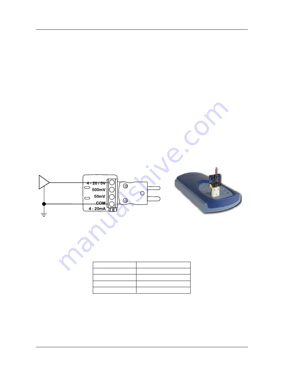
Connect the negative side of your circuit to the COM terminal.
2)
Connect the positive side of your circuit to the “5 V”, “500 mV” or “50 mV”
terminal depending on the voltage range of the signal. For a 4-20 mA loop
signal, use the “5 V” input.
3)
For a 4-20 mA loop signal, set the switch to “ON”. For a voltage signal, set the
switch to “OFF”.
4)
Plug the terminal board into the USB TC-08.
5)
Connect the USB TC-08 to the computer using the USB cable supplied with the
logger.
6)
Run PicoLog on the computer.
7)
Go to File -> New Settings.
8)
Set the converter type to USB TC-08.
9)
Edit one of the USB TC-08 channels and set the “Thermocouple” control to
“mV”.
10)
PicoLog will display the voltage or current applied to the terminal board in the
monitor window.
The voltage displayed in PicoLog corresponds to the input voltage as follows:
Input range
PicoLog voltage
0 – 5 V
0 – 50 mV
0 – 500 mV
0 – 50 mV
0 – 50 mV
0 – 50 mV
4 – 20 mA
9.6 – 48 mV
Figure 1: Example connection for
measuring a 0 to 5 volt signal
Figure 2: The terminal
board fitted to the USB
TC-08


