background image

Connecting the System

PIEGA P SUB 1 MKII

Configuration example for stereo and surround mode

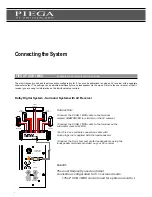
Dolby Digital System - Surround System with NF Out

The 5.1 receivers and power amplifiers of some manufacturers have a separate NF Out terminal. The terminal allows the signal 

to reach the subwoofer without any amplification. Refer to the appropriate manual for information about operation and connection 

options for your AV receiver/power amplifier. 

Note:

Frequently used configuration

                           >Ideal configuration for stereo mode...! 

CROSSOVER

FREQUENCY

40Hz

140Hz

LFE / IN

INPUT

OUTPUT

L

R

60Hz

PRE OUT

L

R

Right

Left

230V

T3. 15AL250V FOR 230V INPUT

T5AL250V FOR 115V INPUT

115/230V - 50/60HZ 500W

Front

Speaker R

Front

Speaker L

Center

Speaker

Rear

Speaker R

Rear

Speaker L

Amplifier

L+

L-

R+

R-

SPEAKER LEVEL INPUTS

Connection:

>Connect the P SUB 1 MKII cable to the AV receiver terminal 

marked PRE OUT (or similar)

>Connect the P SUB 1 MKII cable to the subwoofer terminal 

marked INPUT 

>For this use connection cables with cinch plugs (not supplied) 

>Connect the loudspeakers using the loudspeaker terminals provided 

on your AV receiver/power amplifier 

9

Summary of Contents for P SUB 1 MKII

Page 1: ...User Manual PIEGA P SUB 1 MKII Active Subwoofer Version 1 0...

Page 2: ...at is based on twenty years of R D and which in terms of its design represents the state of the art We are sure that you will gain much listening enjoyment from your new Piega loudspeaker products Alt...

Page 3: ...tics Setting options for individual requirements 14 Daily Use Care and maintenance 15 Warranty Conditions Service and warranty conditions Other configuration examples can be obtained from www piega ch...

Page 4: ...efully and pay special attention to the following precautions and warnings In your own interest we advise you to strictly observe the following procedure when installing your new PIEGA P SUB 1 MKII Wa...

Page 5: ...over 180 once more so that it is standing on the feet provided Check that the P SUB 1 MKII has not been damaged in transit Then place the P SUB 1 MKII in the required position Special care was taken...

Page 6: ...ects such as vases etc on the P SUB 1 MKII so as avoid the possibility of accidents The P SUB 1 MKII can be installed flexibly and easily Due to its relatively small size it can be integrated in any u...

Page 7: ...the following pages The LFE IN INPUT OUTPUT terminals for connecting to the AV receiver or the stereo amplifier require connection cables with cinch plugs The SPEAKER LEVEL INPUT terminals for connect...

Page 8: ...for information on the individual setup controls Connecting the System Benefit The most frequently used and ideal connection configuration for 5 1 surround mode The P SUB 1 MKII can be tuned for opti...

Page 9: ...configuration Ideal configuration for stereo mode CROSSOVER FREQUENCY 40Hz 140Hz LFE IN INPUT OUTPUT L R 60Hz PRE OUT L R Right Left 230V T3 15AL250V FOR 230V INPUT T5AL250V FOR 115V INPUT 115 230V 5...

Page 10: ...e System Benefit Preferred configuration in the high end range The loudspeakers are relieved in the deep bass range CROSSOVER FREQUENCY 40Hz 140Hz LFE IN INPUT OUTPUT L R L L R R SPEAKER LEVEL INPUTS...

Page 11: ...Connect the P SUB 1 MKII cable to the subwoofer terminal marked SPEAKER LEVEL INPUTS Connect the P SUB 1 MKII subwoofer cable to the amplifier terminal marked SPEAKER or similar Likewise connect up th...

Page 12: ...tion Connect the P SUB 1 MKII subwoofer cable to your stereo amplifier at the terminal marked SPEAKER or similar Connect the P SUB 1 MKII cable to the subwoofer terminal marked SPEAKER LEVEL INPUTS Li...

Page 13: ...er to In Phase or Out of Phase Depending on the type of loudspeaker there will be a phase cancelling little bass or a phase correction normal bass Factory setting 0 PHASE SHIFT Use this knob to adjust...

Page 14: ...maintenance Daily Use Procedure Clean the surface of the P SUB 1 MKII with a soft fluff free cloth If necessary the P SUB 1 MKII can be cleaned with a vacuum cleaner set to the lowest power setting Ne...

Page 15: ...horized to do this by Piega 6 If it is necessary for a device or part of it to be sent to Piega or an approved Piega workshop the sender is responsible for paying all transport costs in advance The or...

Page 16: ...SA Switzerland Design by Piega All rights reserved v1 0 040507 Subject to modification in particular technical modifications All specifications without guarantee PIEGA SA Bahnhofstrasse 29 CH 8810 Hor...

Reviews: