TPP
INSTRUCTION MANUAL
Page 14
Date rev. 28/05/13
Rev. 07
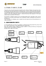
7.
SERVICING AND MAINTENANCE
7.1
NORMAL SERVICING
DAILY :
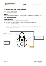
Remove any residual cut material found between the gaps in the head with a compressed air gun.
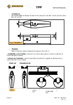
7.2 SPECIAL SERVICING
EVERY 4 MONTHS :
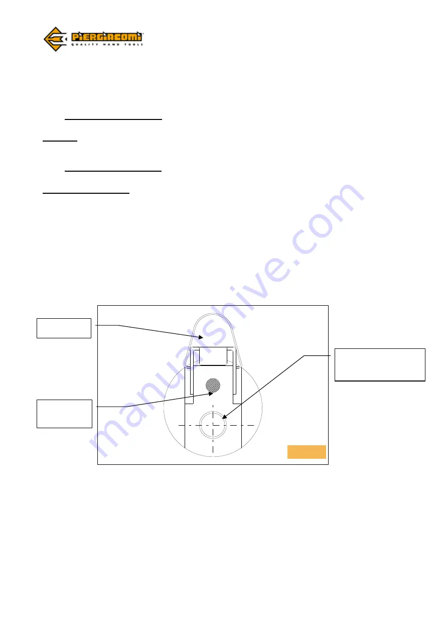
Lubricate the air seals with vaseline oil following the instructions.
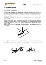
1
Remove the compressed air feed tube, put one cubic centimetre of oil in the air
connector as shown in the Fig.18;
2
Reconnect the compressed air supply tube to the tool and activate the tool several times to
permit the oil to enter in circulation; if the blade slides freely, the lubrification has been a
success, otherwise repeat stage 1.
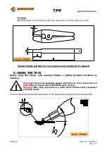
HOOK
COMPRESSED AIR
CONNECTOR Ø6
AIR
SILENCER
Fig. 18


