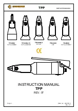
background image


TPP            

INSTRUCTION MANUAL 


Page 3 


                                    Date rev. 28/05/13 


Rev. 07 


1.


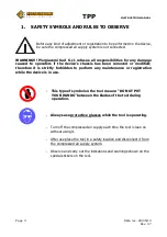
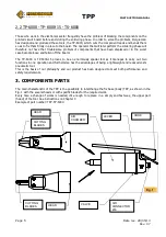
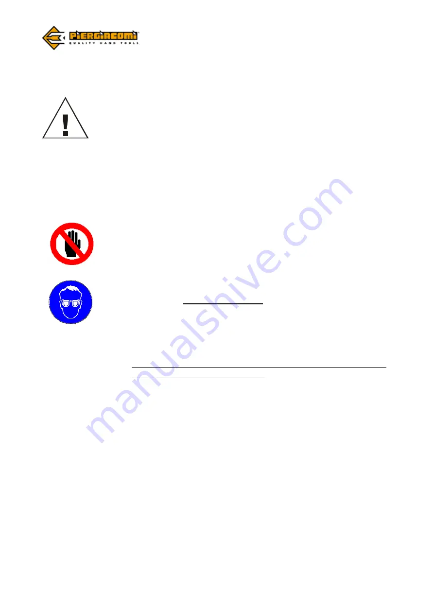
SAFETY SYMBOLS AND RULES TO OBSERVE 


Before any kind of adjustment or registration to be performed on the device, 
be sure the compressed air supply system is not connected.  


WARNING!!!  Piergiacomi  Sud  S.r.l.  refuses  all  responsibilities  for  any  damage 
caused  to  operators  if  the  device’s  chassis  has  been  removed  or  modified; 
therefore  it  is  strictly  forbidden  to  perform  any  maintenance  or  registration 
while the device is in use. 


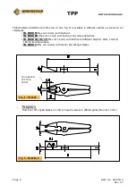
-    This type of symbol on the tool means: “DO NOT PUT 

YOUR HANDS” between the blades of the tool during 
operation. 


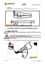
Always use protective glasses while the tool is operating.  


Turn off the compressed air supply each time the tool is lean on  
without using it. 


After use place the tool in a safety location and disconnect it from 
the compressed air supply system.   


Observe and carry out the indications and warnings shown on the 
special stickers on the tool.


Summary of Contents for TP-6000

Page 1: ...TPP INSTRUCTION MANUAL Page 1 Date rev 28 05 13 Rev 07 INSTRUCTION MANUAL TPP REV 07 TP 6000 CUT and BEND TP 6000 15 CUT and BEND TS 6000 CUT and CRIMP TR 6000 CUT TR 6000 V 60 CUT...

Page 2: ...5 Components parts Chapter 4 Page 7 Blade specifications Chapter 5 Page 10 Using the tool Chapter 6 Page 13 Servicing and maintenance Chapter 7 Page 14 How to change blades Chapter 8 Page 15 Optional...

Page 3: ...or modified therefore it is strictly forbidden to perform any maintenance or registration while the device is in use This type of symbol on the tool means DO NOT PUT YOUR HANDS between the blades of...

Page 4: ...ct has been designed to meet both performance and safety requirements Example At the end of the component mounting stage of an electronic printed circuit board the requirement of cutting multiple lead...

Page 5: ...off the board The TP 6000 or TP 6000 15 proves to be an enormously special tool as it manages to carry out two functions in one operation and furthermore has the advantages of being a lightweight and...

Page 6: ...TPP INSTRUCTION MANUAL Page 6 Date rev 28 05 13 Rev 07 3 1 TPP 3 2 TP 6000 TP 6000 15 Fig 2 Fig 3...

Page 7: ...00 V TS 6000 4 BLADE SPECIFICATIONS The blades are made from grinded tempered special steel and can be easily replaced as explained in Chapters 7 of this manual TP 6000 Cut Bend blades for blocking th...

Page 8: ...000 Blades TR 6000 are supplied standard with 2 typology of cuts Fig 7 CHAMFERED code TR 6000 permit also to cut harder components a number of unlimited cuts without damaging the blades FLUSH code TR...

Page 9: ...ith flush cut TR 6000 PR Max cut 1 3 mm with flush cut but more pointed tips TR 6000 10 13 15 Max cut 1 6 mm with flush cut at different height 1 0mm 1 3mm 1 5mm from the surface TR 6000 C Max cut 1 6...

Page 10: ...ore using this device read carefully Chapter 1 Safety Symbols and Rules to observe Warning Always wear protective glasses during the use of the tool and do not work with your fingers close to the blad...

Page 11: ...TPP INSTRUCTION MANUAL Page 11 Date rev 28 05 13 Rev 07 TR 6000 The most suggested point for cutting is situated at about 1 3 of the cutting length see Cap 4 Fig 8 Fig 12 TP 6000 15 Fig 13 TR 6000...

Page 12: ...TPP INSTRUCTION MANUAL Page 12 Date rev 28 05 13 Rev 07 Fig 15 TS 6000 Fig 14 TR 6000 V...

Page 13: ...reassemble the blade insert the blade set as indicated on the Fig 16 and fasten screw M3 M3 SCREWS Fig 16 Use the supplied hexagonal key a slotted screwdriver to remove the ring nut and the M4 screw a...

Page 14: ...te the air seals with vaseline oil following the instructions 1 Remove the compressed air feed tube put one cubic centimetre of oil in the air connector as shown in the Fig 18 2 Reconnect the compress...

Page 15: ...ype of bend 90 TP 6000 or 30 TP 6000 15 Max cut 1 mm TP 6000 TP 6000 15 1 3 mm TS 6000 TR 6000 PR TR 6000 V 1 6mm TR 6000 TR 6000 C TR 6000 10 13 15 Approximate dimensions 165 x 35 mm Weight 300 g TEC...

Page 16: ...tic depaneling machine form 1 to 3 pneumatic heads THE MACHINES SSF 1 DPB 1 and SDP ARE CONFORM TO THE ESSENTIAL REQUIREMENTS OF THE FOLLOWING STANDARD OR HARMONIZING RULES DIRECTIVE 98 37 CE EN 12100...

Reviews: