background image


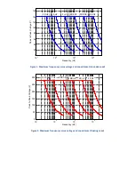
Figure


1.


Maximum


frequency


versus


voltage


and


capacitance


(Grounded


Load)


Figure


2.


Maximum


frequency


versus


voltage


and


capacitance


(Floating


Load)


10

1

10

2

10

3

10

4

0

20

40

60

80

100

120

140

160

Frequency (Hz)

P

ea

k to

 P

ea

Vo

lta

ge

 (

V

)

10

1

10

2

10

3

10

4

0

50

100

150

200

250

300

Frequency (Hz)

Pe

ak

 to

 Pe

ak

 V

ol

ta

ge

 (

V

)

100


nF

300


nF

1


uF

3


uF

10


uF


30


nF


100


nF

300


nF

1


uF


3


uF


10


nF


30


nF

Summary of Contents for PD32

Page 1: ...PD32 32 Channel Piezo Driver Manual and Specifications PiezoDrive Pty Ltd www piezodrive com ...

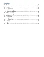
Page 2: ...e Range 5 4 1 Ground load configurations 5 4 2 Floating load configuration 6 5 Input Connection Diagram 6 6 Output Connection Diagram 7 7 Output Current 8 8 Power Bandwidth 8 9 Small Signal Bandwidth 10 10 Overload Protection 11 11 Enclosure 11 12 Signal Adaptors 11 13 Waranty 11 ...

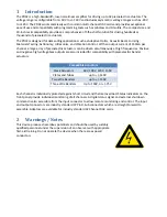
Page 3: ...sly at high frequencies Positive and negative high voltage bias outputs are also included for compatibility with piezoelectric bender actuators Compatible Actuators Stack Actuators 60V 100V 120V 150V Plates and Tubes up to 140V Two Wire Benders up to 140V Three Wire Benders Up to 140V or 75V Each channel is individually protected against short circuit and thermal overload Status indicators on the ...

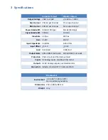
Page 4: ... Rate 19 V us 38 V us Gain 15 V V 30 V V Input Impedance 53 kOhm 6 25 kOhm Input Offset 5 mV 5 mV Load Unlimited Unlimited Output Noise 200 uV RMS 1uF Load 300 uV RMS 1uF Load Protection Short circuit and thermal overload Inputs 32 Analog inputs shutdown command Outputs 32 HV Analog outputs overload monitor Connectors Industry standard 37 Pin Female D Sub Mechanical Environment 40 to 60 C 40 to 14...

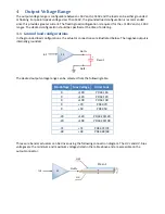
Page 5: ...e grounded load configurations the actuator connections are illustrated below The negative output is internally grounded The desired output voltage range can be selected from the following table Min Voltage Max Voltage Order Code 0 140 PD32 140 0 120 PD32 120 0 100 PD32 100 0 70 PD32 70 0 50 PD32 50 20 120 PD32 20 120 20 100 PD32 20 100 72 72 PD32 72 72 48 48 PD32 48 48 Three wire bender actuators...

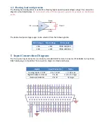
Page 6: ...selected from the following table Min Voltage Max Voltage Order Code 140 140 PD32 140 140 100 100 PD32 100 100 5 Input Connection Diagram The front panel input connector is an industry standard DB37 Female Connector TE 1658612 1 Any Male DB37 cable plug is compatible The connection diagram is illustrated below Signals Input Connector Notes Analog Inputs 1 to 32 Pins 1 to 32 10V max Digital disable...

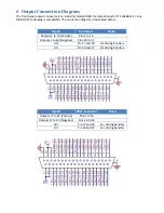
Page 7: ...m is illustrated below Signals Connector 1 Notes Outputs 1 to 16 Positive Pins 1 to 16 Outputs 1 to 16 Negative Pins 20 to 35 HV Pin 17 and 18 For driving benders HV Pin 36 and 37 For driving benders Signals DB37 Connector Notes Outputs 17 to 32 Positive Pins 1 to 16 Outputs 17 to 32 Negative Pins 20 to 35 HV Pin 17 and 18 For driving benders HV Pin 36 and 37 For driving benders ...

Page 8: ...by the output current The maximum frequency sine wave is where is the peak current limit is the peak to peak output voltage and is the effective load capacitance The power bandwidth versus load capacitance is listed below Load Peak to Peak Voltage Grounded Cap 50 100 140 10 nF 95 kHz 47 kHz 34 kHz 30 nF 31 kHz 15 kHz 11 kHz 100 nF 9 5 kHz 4 7 kHz 3 4 kHz 300 nF 3 1 kHz 1 5 kHz 1 1 kHz 1 uF 950 Hz ...

Page 9: ...requency versus voltage and capacitance Floating Load 10 1 10 2 10 3 10 4 0 20 40 60 80 100 120 140 160 Frequency Hz Peak to Peak Voltage V 10 1 10 2 10 3 10 4 0 50 100 150 200 250 300 Frequency Hz Peak to Peak Voltage V 100 nF 300 nF 1 uF 3 uF 10 uF 30 nF 100 nF 300 nF 1 uF 3 uF 10 nF 30 nF ...

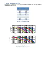
Page 10: ...Capacitance Signal Bandwidth No Load 120 kHz 10 nF 90 kHz 30 nF 40 kHz 100 nF 11 kHz 300 nF 3 8 kHz 1 uF 1 0 kHz 3 uF 320 Hz 10 uF 62 Hz 30 uF 24 Hz Table 2 Small signal bandwidth 3 dB Figure 3 Small signal frequency response 10 2 10 3 10 4 10 5 0 10 20 30 Magnitude dB 10 2 10 3 10 4 10 5 150 100 50 0 Phase deg Frequency Hz 100 nF 300 nF 1 uF 3 uF 10 uF 30 nF 10 nF ...

Page 11: ...ment with another adaptor or the amplifier itself A single amplifier or adaptor can be mounted with the PD32 Rack1 kit Two adaptors amplifiers or a combination of both can be mounted side by side with the PD32 Rack2 kit 12 Signal Adaptors The signal adaptors allow a direct connection to common multi channel DAC cards Standard adaptors are listed below however custom adaptors can also be created Ma...

Reviews: