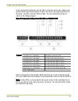
to the quad with the Slammer and the Pilot, so that the load for the middle quad
with two Bricks and one Slammer is 8.22A. The load on the right quad with one
Slammer, one Brick, and one Pilot is 5.99A. You can distribute the plugs as
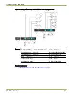
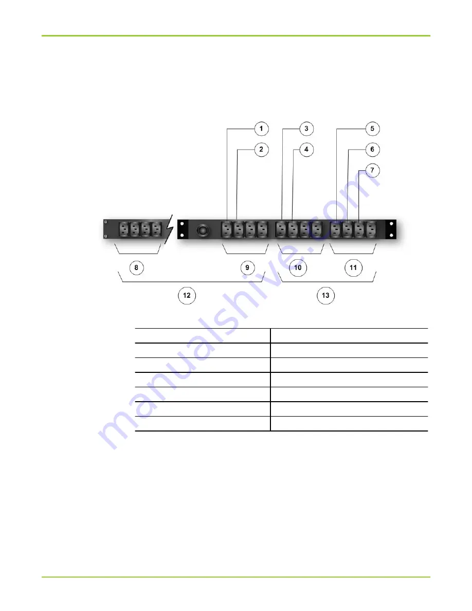
shown in the following figure:
Figure 51 Sample power cabling scheme with 115V on a TCP2105-1 PDU
Legend
1 SATA Brick 1: 2.12Adrawn
8 No amps. drawn for group
2 SATA Brick 2: 2.12A drawn
9 Total of 4.24A drawn for group
3 SATA Brick 3: 2.12A drawn
10 Total of 4.24A drawn for group
4 SATA Brick 4: 2.12A drawn
11 Total of 6.29A drawn for group
5 Slammer CU 0: 2.42A drawn
12 Total of 4.24A drawn for group
6 Slammer CU 1: 2.42A drawn
13 Total of 10.53A drawn for groups
7 Pilot: 1.45A drawn
Other configurations are possible. Make sure that you do not exceed the rating
for a four-outlet bank or the rating for a set of two banks, which is 12A for this PDU.
Note: Another PDU is still needed for the power cords for the redundant circuit,
which was left out of the above figures for simplicity. The redundant PDU should
be cabled the same way.
Chapter 5 Connect Power Cables
About Power Cabling
111

