background image


83

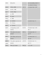
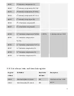
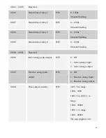
40618 

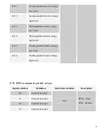
Minimum phase C current   

RO 

40619 

Minimum total active power 

low word   

RO 

40620 

Minimum total active power 

high word 

RO 

Calculation factor: 0.1, 

unit: W 

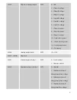
40621 

Minimum total reactive 

power low word 

RO 

40622 

Minimum total reactive 

power high word 

RO 

Calculation factor: 0. 1, 

unit: Var 

40623 

Minimum total apparent power 

low word 

RO 

40624 

Minimum total apparent 

power high word 

RO 

Calculation factor: 0.1, 

unit: VA 

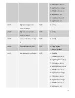
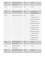
40625 

Minimum Ia-THD 

RO 

40626 

Minimum Ib-THD 

RO 

40627 

Minimum Ic-THD 

RO 

40628 

Minimum Va-THD 

RO 

40629 

Minimum Vb-THD   

RO 

40630 

Minimum Vc-THD   

RO 

Calculation factor: 0.001 


Summary of Contents for PMAC735

Page 1: ...PMAC735 Multifunction Measuring Meter Installation Operation Manual V8 2 ZHUHAI PILOT TECHNOLOGY CO LTD...

Page 2: ...be installed and maintained only by qualified people Before operating the device isolate the voltage input and power supply and short circuit the secondary windings of all current transformers Put al...

Page 3: ...2 2 Dimension 10 2 3 Description of the main unit terminals 11 2 4 Description of extension module terminals 12 2 5 Order information 16 2 6 Connection 17 3 Measuring Capability 20 3 1 Real time basi...

Page 4: ...ister reading 65 8 5 Register setting 66 8 6 Description of data types 67 8 7 Calculation factors 67 8 8 Communication values and actual values 68 8 9 List of universal data registers 69 8 10 List of...

Page 5: ...5 8 17 List of energy setting registers 91 8 18 05H command control relays 92 9 Maintenance and Trouble Shooting 93 10 Technical Datasheet 96...

Page 6: ...ta on the site PMAC735 is really a measuring meter based on true effective values able to carry out accurate measurement of highly non linear loads The complicated sampling technology enables it to me...

Page 7: ...7 1 1 Pictures of the main unit Side view Rear view 1 2 Picture of the extension module Rear view...

Page 8: ...FIBUS communication port Notes 1 Each PMAC735 main unit can be equipped with one extension module at most 2 Digital input requires external dry contact 3 The capacity of each relay output node is 250...

Page 9: ...n Measurement of THD and K factor Build in clock Demand calculation and maximum recording Large high contrast LCD screen easy for operating and setting with password lock Revisable fixed value alarm a...

Page 10: ...1 Storage temperature 30 70 2 Operating temperature 20 60 3 Humidity 5 90 non condensing 2 2 Dimension Panel size 96 00 96 00 mm Installation size 89 50 89 50 mm Depth 65 00 mm the depth will be incre...

Page 11: ...Null 18 NC Null 5 FG Earth protection 19 NC Null 6 NC Null 20 A1 Positive analog output 7 21 AG Negative analog output 8 22 VN Voltage neutral line 9 I32 Phase C current outgoing line 23 NC Null 10 I3...

Page 12: ...utput 36 R11 Positive relay 1 output 30 R41 Positive relay 4 output 37 Scom Positive status 30V power supply 31 R32 Negative relay 3 output 38 S4 Status 4 input 32 R31 Positive relay 3 output 39 S3 St...

Page 13: ...t 36 S6 Status 6 input 30 R21 Positive relay 2 output 37 S5 Status 5 input 31 R12 Negative relay 1 output 38 S4 Status 4 input 32 R11 Positive relay 1 output 39 S3 Status 3 input 33 Scom Positive stat...

Page 14: ...tus 6 input 30 P2 Positive reactive energy pulse output 37 S5 Status 5 input 31 P1 Negative active energy pulse output 38 S4 Status 4 input 32 P1 Positive active energy pulse output 39 S3 Status 3 inp...

Page 15: ...Null 31 P Positive pole of profibus 38 NC Null 32 RA Terminal resistor A 39 NC Null 33 SHLD Communication shielded earth 40 NC Null 34 NC Null 41 NC Null 35 NC Null 42 NC Null Remark There should be a...

Page 16: ...and voltage THD K factor SOE event log One 4 20 mA analog output Code A D AC85 265V 50Hz 60Hz DC80 300V DC24 48V Code V1 V2 V3 V4 V5 V6 V7 V8 Rated Voltage Current Input 57 7 100V 5A Rated Voltage Cur...

Page 17: ...module 4 status inputs 4 relay outputs harmonic analysis one 4 20 mA analog output rated measurement of 220 V 380 V 5 A Basic Module Real time measurement and energy measurement Demand and its maximu...

Page 18: ...18 B Low voltage 3 phase 3 wire delta connection 3 CTs C Low voltage 3 phase 3 wire delta connection 2 CTs...

Page 19: ...19 D High voltage 3 phase 4 wire star connection E High voltage 3 phase 3 wire delta connection 3 CTs...

Page 20: ...al parameters PMAC735 provides voltage current power and frequency etc basic parameters The following data are effective real values and the refresh rate is 1 second Real time reading Measuring range...

Page 21: ...ower Single phase 0 100 MW Var VA Total 0 100 MW Var VA Power factor Single phase 1 000 1 000 Total 1 000 1 000 Frequency 35 65 Hz 35 65 Hz 3 2 Power factor symbols The symbols of measuring power fact...

Page 22: ...e divided by the time length To facilitate the operation of the user PMAC735 adopts the fixed block calculation method in the fixed period of time and the period of time is fixed being 15 minutes PMAC...

Page 23: ...999 9 The decimal place will not show When the accumulated value reaches to maximum it will overturn automatically The polarity of energy is identical to that of power both conforming to the stipulat...

Page 24: ...power 3 5 Harmonic parameters optional PMAC735 provides optional measurement of complete 31st harmonic for voltage and current as well as their total harmonic content THD and K factor of current The...

Page 25: ...tive value of each harmonic to that of the fundamental harmonic n Highest harmonic order which should be 31 here Attention 1 Each harmonic and THD can be checked through display or communication 2 K f...

Page 26: ...Energy programming data area H Energy unit I Relay status indication K Status state indication L Energy pulse function prompt M Energy quadrant prompt O Programming indication P Real time data type i...

Page 27: ...Menu turning up Increase the numeric value at the cursor Energy page turning Press the key Enter to enter into modification Press the key Enter to confirm the modification Enter into programming inte...

Page 28: ...rent power demand and maximum value Total voltage harmonic THD Component of each voltage harmonic Total current harmonic THD Component of each current harmonic Line voltage Phase current Main menu Sub...

Page 29: ...4 4 2 1 Voltage data query Press the key continuously and you will see the following items one by one a Line voltage V A B C A B C S1 S2 S3 S4 RL1 RL2 RL3 RL4 b Line voltage unbalance rate A B C A B C...

Page 30: ...Current unbalance rate c Neutral current A A C B S1 S2 S3 S4 RL1 RL2 RL3 RL4 S1 S2 S3 S4 RL1 RL2 RL3 RL4 U nbal A S1 S2 S3 S4 RL1 RL2 RL3 RL4 4 2 3 Active power data query 1 Press the key once and yo...

Page 31: ...ower data query 1 Press the key once and you will see the total three phase apparent power S1 S2 S3 S4 RL1 RL2 RL3 RL4 2 Press the key continuously and you will see the single phase apparent power A C...

Page 32: ...32 4 2 7 Frequency Press the key once and you will see the frequency data S1 S2 S3 S4 RL1 RL2 RL3 RL4...

Page 33: ...nd is displayed as below format 1st row year month 2nd row day hour 3rd row minute second a Current demand and maximum value M A X D M D A S1 S2 S3 S4 RL1 RL2 RL3 RL4 b Time record of maximum current...

Page 34: ...M D S1 S2 S3 S4 RL1 RL2 RL3 RL4 h Time record of maximum apparent power demand D M D S1 S2 S3 S4 RL1 RL2 RL3 RL4 M A X 4 2 9 Voltage harmonic query 1 Press the key once and you will see the voltage ha...

Page 35: ...ic take the component of the 28th harmonic as an example A C B S1 S2 S3 S4 RL1 RL2 RL3 RL4 4 2 11 Maximum value recording 1 Press the key once and you will see the Maximum value of real time data 2 Pr...

Page 36: ...T H D f Maximum value of voltage THD A C B S1 S2 S3 S4 RL1 RL2 RL3 RL4 M A X T H D 4 2 12 Minimum value recording 1 Press the key once and you will see the minimum value of real time data 2 Press the...

Page 37: ...t THD S1 S2 S3 S4 RL1 RL2 RL3 RL4 M I N T H D A C B f Minimum value of voltage THD M I N S1 S2 S3 S4 RL1 RL2 RL3 RL4 T H D A C B 4 2 13 Energy data query In any query interface press the key continuou...

Page 38: ...rant reactive energy S1 S2 S3 S4 RL1 RL2 RL3 RL4 f Second quadrant reactive energy S1 S2 S3 S4 RL1 RL2 RL3 RL4 g Third quadrant reactive energy S1 S2 S3 S4 RL1 RL2 RL3 RL4 h Fourth quadrant reactive e...

Page 39: ...S1 S2 S3 S4 RL1 RL2 RL3 RL4 If the meter has the clock function then in any query interface press the key continuously you will see the following items after the energy one by one Year month and day...

Page 40: ...its are reserved The fifth digit diagnosis of sampling reference point The sixth digit diagnosis of configuration parameter The seventh digit diagnosis of accuracy coefficient The eighth digit diagnos...

Page 41: ...ress the key until CT PR appears 2 Press the key and the cursor appears 3 Press the key to modify the value 4 Press the key to confirm the new value and the cursor disappears CT primary side can be se...

Page 42: ...g 1 Press the key until PT SE appears 2 Press the key and the cursor appears 3 Press the key to modify the value 4 Press the key to confirm the new value and the cursor disappears PT secondary side ca...

Page 43: ...1 Press the key until BAUD appears 2 Press the key and the cursor appears 3 Press the key to select 4800 9600 19200 or 38400 4 Press the key to confirm the selection and the cursor disappears The max...

Page 44: ...g maximum value of demand 1 Press the key until CLR D appears 2 Press the key and the cursor appears 3 Press the key to select YES or NO 4 Press the key to confirm the selection and the cursor disappe...

Page 45: ...ntil P1 ob appears 2 Press the key and the cursor appears 3 Press the key to select nULL or IMP or EXP 4 Press the key to confirm the selection and the cursor disappears Object of reactive energy puls...

Page 46: ...ify value 4 Press the key to confirm new value and the cursor disappears Note 1 P1 ob refers to the setting for object of active energy pulse output 2 P2 ob refers to the setting for object of reactiv...

Page 47: ...ut please re start the device PMAC735 Multiple of analog output 1 Press the key until An MU appears 2 Press the key and the cursor appears 3 Press the key to modify value 4 Press the key to confirm ne...

Page 48: ...be able to look up the mode and return time value of each relay Relay 1 Control mode 1 Press the key until R1 MO appears 2 Press the key and the cursor appears 3 Press the key to select RE or LOCAL 4...

Page 49: ...Relay 3 Control mode 1 Press the key until R3 MO appears 2 Press the key and the cursor appears 3 Press the key to select RE or LOCAL 4 Press the key to confirm the selection and the cursor disappear...

Page 50: ...e 1 Press the key until R4 RE appears 2 Press the key and the cursor appears 3 Press the key to modify the value 4 Press the key to confirm the new value and the cursor disappears Recover system defau...

Page 51: ...ified Password modification 1 Press the key until CODE appears 2 Press the key and the cursor appears 3 Press the key to modify the value 4 Press the key to confirm the new value and the cursor disapp...

Page 52: ...provides is not below 30V On the site dry nodes or passive auxiliary nodes can be connected directly When external nodes are closed the corresponding status input channels will be closed 4 status inpu...

Page 53: ...response to the control alarm conditions of a set point Once the relay has been in the remote control mode even though the local control conditions have been set the relay will not operate The relay m...

Page 54: ...y is generated the relay operates The relay s operating status will be kept within the period of time for timing When the timer overflows the relay will be released and kept released 5 3 Pulse outputs...

Page 55: ...uts should be multiplied by the CT and PT factors Each pulse does not represent one kilowatt hour or kilovar hour so the user needs to set a reasonable pulse constant The maximum setting range is betw...

Page 56: ...load resistance of the interface should not exceed 500 Ohms On some sites due to different transmission cables or loading conditions the analog output at the high end appears to be non linear PMAC735...

Page 57: ...ue of the analog quantity unit mA e P Corresponding rated power value unit W Var Magnification factor of the corresponding channel Its range is between 1 and 10 e e e I U P 3 Where e U Rated line volt...

Page 58: ...ne AB voltage Line BC voltage Line CA voltage Current Phase A current Phase B current Phase C current Active power Total active power Reactive power Total reactive power Power factor Total power facto...

Page 59: ...se line voltage 4 Minimum value of three phase line voltage 5 Maximum value of three phase current 6 Minimum value of three phase current Operation upper limit value 0 120 of rated value Operation low...

Page 60: ...er limit value 80 it is assumed here that under voltage refers to a voltage lower than 80 of the rated voltage Operation time 0 s Return time 0 s Other values can be set according to the above procedu...

Page 61: ...and the resolution is 2 ms Users can read all the SOE records through communication For details refer to SOE event log A standard structure of SOE event data is as follows No of the relative byte Defi...

Page 62: ...The length of the functional code field is 1 byte used to tell the slave station to execute what operations The functional codes supported by PMAC735 are listed in the table below Functional code Mea...

Page 63: ...alid data register an abnormal data response will be generated This abnormal data response is composed of the slave station address functional code trouble code and check field When the highest bit of...

Page 64: ...duced by analogy Sending sexadecimal FF 00 closes a relay and sending sexadecimal 00 00 releases a relay All the other values will be invalid Control relay format Main station PMAC735 Response format...

Page 65: ...e format PMAC735 main station Slave station address 1 byte Slave station address 1 byte Functional code 03H 1 byte Functional code 03H 1 byte Start address 2 bytes Byte number 2 number of registers 1...

Page 66: ...PMAC735 Response format PMAC735 main station Slave station address 1 byte Slave station address 1 byte Functional code 10H 1 byte Functional code 10H 1 byte Start address 2 bytes Start address 2 byte...

Page 67: ...channel The rest bits may be deduced by analogy Bit 0 refers to off and bit 1 refers to on 8 7 Calculation factors Due to the restriction of the value ranges many of the data registers of PMAC735 use...

Page 68: ...l voltage Secondary side Communication value calculation factor PT 2 Per phase current Average phase current Neutral current Current demand minimum maximum value Secondary side Communication value cal...

Page 69: ...it V 40007 Phase A current 40008 Phase B current 40009 Phase C current 40010 Neutral current UNIT16 Calculation factor 0 001 unit A 40011 Three phase active power low word 40012 Three phase active pow...

Page 70: ...ord Calculation factor 0 1 unit kwh 40021 Input reactive energy low word 40022 Input reactive energy high word Calculation factor 0 1 unit kvarh 40023 Output active energy low word 40024 Output active...

Page 71: ...K factor 40037 Ic K factor UINT16 Calculation factor 0 1 40038 Average phase current demand UNIT16 Calculation factor 0 001 unit A 40039 40040 Three phase active power demand Calculation factor 0 1 u...

Page 72: ...e BC voltage 40108 Line CA voltage Calculation factor 0 01 unit V 40109 Line voltage unbalance rate Calculation factor 0 001 40110 Average line voltage 40111 Neutral voltage UINT16 Calculation factor...

Page 73: ...126 Total reactive power low word 40127 Total reactive power high word LINT32 Calculation factor 0 1 unit Var 40128 Phase A apparent power 40129 Phase B apparent power 40130 Phase C apparent power UIN...

Page 74: ...136 Total power factor 40137 Frequency UINT16 Calculation factor 0 01 unit Hz 40138 On off status 40139 Relay status WORD16 When any bit is 0 that means the corresponding contact is cut otherwise is c...

Page 75: ...active energy low word 40206 Output active energy high word Calculation factor 0 1 unit kwh 40207 Output reactive energy low word 40208 Output reactive energy high word Calculation factor 0 1 unit kv...

Page 76: ...quadrant reactive energy high word 40219 Second quadrant reactive energy low word 40220 Second quadrant reactive energy high word 40221 Third quadrant reactive energy low word 40222 Third quadrant rea...

Page 77: ...word 40305 Total reactive power demand high word LINT32 Calculation factor 0 1 unit Var 40306 Total apparent power demand low word 40307 Total apparent power demand high word LUINT32 Calculation fact...

Page 78: ...ow byte hour 40316 Time of max total active power demand minute second UNIT16 High byte minute low byte second 40317 Maximum total reactive power demand low word 40318 Maximum total reactive power dem...

Page 79: ...Calculation factor 0 1 unit VA 40324 Date of max total apparent power demand year month UNIT16 High byte year low byte month 40325 Time of max total apparent power demand day hour UNIT16 High byte day...

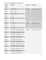
Page 80: ...IT16 Calculation factor 0 1 40410 2nd harmonic component of Va Vab 40411 2nd harmonic component of Vb Vbc 40412 2nd harmonic component of Vc Vca 40413 2nd harmonic component of Ia 40414 2nd harmonic c...

Page 81: ...584 31st harmonic component of Va Vab 40585 31st harmonic component of Vb Vbc 40586 31st harmonic component of Vc Vca 40587 31st harmonic component of Ia 40588 31st harmonic component of Ib 40589 31st...

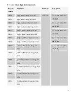
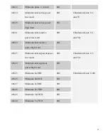
Page 82: ...r 0 1 unit Var 40608 Maximum total apparent power low word RO 40609 Maximum total apparent power high word RO Calculation factor 0 1 unit VA 40610 Maximum Ia THD RO 40611 Maximum Ib THD RO 40612 Maxim...

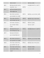
Page 83: ...er low word RO 40622 Minimum total reactive power high word RO Calculation factor 0 1 unit Var 40623 Minimum total apparent power low word RO 40624 Minimum total apparent power high word RO Calculatio...

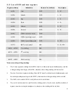
Page 84: ...h event log RO Notes concerning writing reading 1 The 6 time registers starting from 40701 must be written and read simultaneously and the writing reading must begin with 40701 otherwise the writing r...

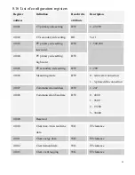
Page 85: ...side setting high word R W 1 500 000 41005 PT secondary side setting R W 1 200 41006 Measuring mode R W 0 4 line star connection 1 3 phase delta connection 41007 Communication address R W 1 247 41008...

Page 86: ...9 Return time of relay 4 R W 0 1200s 0 means blocking 41020 41021 Reserved 41022 Active energy pulse output R W 0 Off 1 Active energy input 2 Active energy output 41023 Reactive energy pulse output R...

Page 87: ...current 10 Total active power 11 Total reactive power 12 Total power factor 13 Frequency 41026 Analog output factor R W 10 100 41027 41030 Reserved 41031 Control mode of relay 1 R W 0 Local control 1...

Page 88: ...value of relay 1 R W 0 120 41035 Action time delay of relay 1 R W 0 1200s 41036 Control mode of relay 2 R W 0 Local control 1 Remote control 41037 Operation object of relay 2 R W 0 Disable 1 Maximum...

Page 89: ...mode of relay 3 R W 0 Local control 1 Remote control 41042 Operation object of relay 3 R W 0 Disable 1 Maximum value of three phase phase voltage 2 Minimum value of three phase phase voltage 3 Maximu...

Page 90: ...ble 1 Maximum value of three phase phase voltage 2 Minimum value of three phase phase voltage 3 Maximum value of three phase line voltage 4 Minimum value of three phase line voltage 5 Maximum value of...

Page 91: ...Second quadrant active energy low word 41104 Second quadrant active energy high word 41105 Third quadrant active energy low word 41106 Third quadrant active energy high word 41107 Fourth quadrant acti...

Page 92: ...14 Third quadrant reactive energy high word 41115 Fourth quadrant reactive energy low word 41116 Fourth quadrant reactive energy high word 8 18 05H command control relays Register address Definition R...

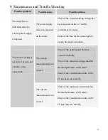
Page 93: ...e control power supply has been burnt down The voltage measurement is not correct Check if the neutral point has been connected reliably Check if the measured voltage matches the rated parameter of th...

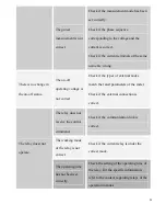
Page 94: ...k if the types of external nodes match the rated parameters of the meter Check if the external connection is correct The relay does not receive the control command Check if the communication link is c...

Page 95: ...re are more than two identical addresses in the same network The communication speed of the meter is not correct Check if the communication speed of the meter is consistent with its definition The com...

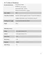
Page 96: ...splay LCD Connection of terminals Standard 5 08 mm pluggable terminals The current terminals are equipped with fasteners to prevent accidental coming off Working power supply 85 265 VAC 45 65 Hz 100 3...

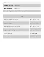
Page 97: ...EMC Electrostatic Discharge Immunity Test IEC 61000 4 2 Level 4 Radiated immunity test IEC 61000 4 3 Level 3 Electrical fast transient burst immunity test IEC 61000 4 4 Level 4 Surge immunity test 1...

Page 98: ...ovement Technical Consulting 86 15916202620 After sale Services 86 15916202800 Email pilot166 pmac com cn Zhuhai Pilot Technology Co Ltd Add No 15 Keji 6 Road Chuangxin Haian Tangjia High tech Zone Zh...

Reviews: