Operating instructions (translation from original IT)
Cod. OQ7_5ARG078EN
Emiss. 18-07-08 Rev. 5 - Agg. 20-04-16
26
13
FIRST START-UP
The first start-up of the compressor (operative test) must obligatorily be carried out by a specialized technician.
Ask the testing technician to fill in the R.C.R. form at the end of the manual. Filling in this form allows you to be sure that a complete
test has been performed and, in the event of malfunctions of any kind, faster and more effective action can be taken under guarantee.
ON-OFF COMPRESSOR
These compressors are provided with a safety device as regards the
direction of rotation
. Running the compressor with the wrong
direction of rotation may damage it seriously and cause the leakage of oil from the intake valve.
To make the first start-up, after installation, turn on the power supply to the electric panel.
If the phases are inverted, the following message will appear on the board display: “INCORRECT ROTATION”.
Proceed as follows:
1.
Switch off the power;
2.
Exchange the connections of the two phases of the compressor power supply line;
3.
Restore power. Consequently also the direction of rotation of the electric fan will be correct.
4.
Reset the alarm by pressing the “RESET” button and start the machine.
If the phases are correct no alarm appears on the display and the machine can be started.
COMPRESSOR ACTIVATED BY AN INVERTER
Compressors with an inverter are equipped with an electronic system to control the
absorbed power
and the
motor temperature
, in
any case it is important to take the greatest care during the
first start-up
to avoid very serious damage to the compressor itself.
To make the first start-up, after installation, turn on the power supply to the electric panel, press the “Start” key and check that the
electric fan is turning in the correct direction, comparing it with the direction indicated by the sticker on the structure. If the direction
is incorrect, proceed as follows:
a)
switch off the machine
b)
switch off the power
c)
exchange the connections of two phases of the electric fan power supply
d)
restart the machine.
FOR THE FIRST START-UP CONSULT THE SPECIFIC INVERTER MANUAL SUPPLIED WITH THE
DOCUMENTATION.
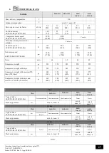
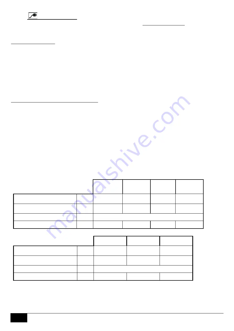
To change the fuses and the electric cables, refer to the following table.
400/50
NEWTON
1307
EDISON
1309 DV
NEWTON
1311
NEWTON
EDISON DV
1315
Input cables minimum section (*)
mm²
10
10
10
16
Electronic board fuses
N° x A
1 x 2
1 x 2
1 x 2
1 x 2
Electric panel fuses
N° x A
Check wiring diagram
Auxiliary / electronic panel voltage
V
110 / 15
110 / 15
110 / 15
110 / 15
230/60
NEWTON
1307
NEWTON
1311
NEWTON
1315
Input cables minimum section (*)
mm²
16
16
25
Electronic board fuses
N° x A
1 x 2
1 x 2
1 x 2
Electric panel fuses
N° x A
Check wiring diagram
Auxiliary / electronic panel voltage
V
110 / 15
110 / 15
110 / 15
(*) Neutral connection if there is a dryer or heater present.


