4.5.Removal of Protective Housing
Caution! You can remove the protective covers only if the MAIN SWITCH is turned off
and secured against restart or if the machine is disconnected from the mains.
Caution: Danger of injury by the sharp teeth of the saw blade. Use protective gloves.
Do not reach between the wheels and the saw blade.
The MAIN SWITCH is turned on, the TOTAL STOP button is unblocked, the SAFETY button is not active. The cutting mode is set to
MANUAL. If the arm is lower than approximately 20 mm above the fixed vice jaw, set the height of the arm uplift to its maximum (see
section 4.9.) and switch the ARM UPLIFT SWITCH to position 0. Press the HYDRAULIC UNIT - START button. Switch the ARM
UPLIFT SWITCH to position 1 and thus raise the arm to its upper position (see section 4.1.). Shut off the control valve of the damper
cylinder (see section 4.2.). Start the arm descent by pressing the button START DESCENT. Lower the saw arm approx. 30 mm
above the fixed vice jaw and using the CONTROL VALVE, secure it against descending. Switch off the POWER SWITCH and secure
it against restart.
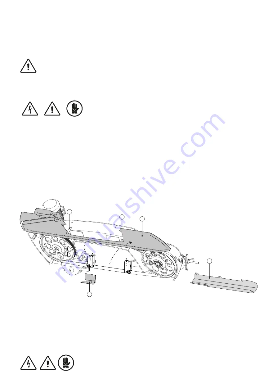
Unscrew the blade cover (D) an place it aside. Unscrew and slide out the cover of the front rod (A), place it aside and unlock the
angled latch. Open the back cover (C) upwards and secure with latches (B). Use a reverse procedure to mount back the protective
covers. Switch on the POWER SWITCH, or connect the machine to the mains. Then press the SAFETY and HYDRAULIC UNIT
START button. The arm is now in an interposition between the limit switches, therefore is it necessary to switch the arm uplift switch
into position 1 in order to unblock the interposition and allow the arm to ascend.
4.4.Arm - Saw Blade Guidance
The saw arm is made of sturdy cast of grey cast iron, which guarantees outstanding stiffness during band tensioning. The saw blade
is guided by two guide heads both behind and in front of the cut. The heads are fitted with eccentrically placed bearings and hardened
steel blade guides that allow easier rewinding of the saw blade as opposed to wheel guidance. The fixed guide block is placed on a
fixed guide bar and the movable guide block is placed on the movable bar. The moving guide block moves towards the cut material by
30-50 mm manually.
Danger of injury - no cover in the machining area!
Caution! You can remove the protective covers only if the MAIN SWITCH is turned off and
secured against restart or if the machine is disconnected from the mains.
Caution: Danger of injury by the sharp teeth of the saw blade. Use protective gloves. Do not
reach between the wheels and the saw blade.
4.6.Replacement, Tensioning and Adjustment of the Saw Blade
A timely replacement of the saw blade is needed to achieve good cutting performance, surface finish quality and compliance with
workpiece dimensions. Blunt saw blades cause high consumption of electrical power, scarf cuts and rough cutting surfaces.One of
the decisive factors affecting the quality of the cut and the life of the cutting tool is the correct and sufficient saw blade tension.
Follow the instructions in section 4.5. in order to remove the protective covers. The machine is switched off and secured against
restart, the arm is locked approximately 30 mm above the fixed vice jaw.
D
A
C
B
B
Summary of Contents for ARG 300 plus S.A.F.
Page 2: ......


