


- 4 -
4. Sicherung wieder zurücksetzen: den
Kurzschluss entfernen und die Versor-
gungsspannung für ca. 1 Minute abschal-
ten.
• Leitungsmaterial aus Kupferdraht mit einer
Temperaturbeständigkeit von 60/75 °C
verwenden.
• Angaben im Kapitel "Technische Daten"
unbedingt einhalten.
Ablauf:
• Verzögerungszeit t1 für Sicherheitskontakt
57-58 und t2 für Sicherheitskontakt 67-68
mit Hilfe eines Schraubendrehers festle-
gen.
• Versorgungsspannung an Klemmen A1 (+)
und A2 (-) anlegen.
• Rückführkreis schließen
Brücke an Y1-Y2 oder externe Schütze
anschließen.
• Aktivierungskreis schließen
- Automatischer Start: S12-S34 brücken.
- Manueller Start: Taster an S12-S34
anschließen (keine Brücke an S12-S34).
• Eingangskreis schließen
- Einkanalig: S21-S22 und S12-S52
brücken. Öffnerkontakt von Auslöse-
element an S11 und S12 anschließen.
- Zweikanalig ohne Querschluss-
erkennung: Öffnerkontakt von Auslöse-
element an S11-S12/S11-S52 anschlie-
ßen, S21-S22 brücken
- Zweikanalig mit Querschlusserkennung:
Öffnerkontakt von Auslöseelement an
S11-S12/S21-S22 anschließen, Y36-
S52 brücken
• Reset-Eingang schließen
- ohne Reset-Funktion: Y39-Y40 brücken.
- mit Reset-Funktion: Öffnerkontakt an
Y39-Y40 anschließen.
Die Sicherheitskontakte sind aktiviert und der
Hilfskontakt (41-42) ist geöffnet. Die Status-
anzeigen leuchten. Das Gerät ist betriebsbe-
reit.
Wird der Eingangskreis geöffnet, öffnen die
Sicherheitskontakte 13-14/23-24/33-34/ und
der Hilfskontakt 41-42 schließt. Die Leucht-
dioden "ch.1" und "ch.2" erlöschen.
Der Sicherheitskontakt 57-58 öffnet sich
nach Ablauf von t1 und Sicherheitskontakt
67-68 nach Ablauf von t2. Die Leuchtdioden
t1 und t2 erlöschen.
Wieder aktivieren:
• Eingangskreis schließen
• Bei manuellem Start zusätzlich Taster
zwischen S12 und S34 betätigen.
Die Statusanzeigen leuchten wieder, die
Sicherheitskontakte sind geschlossen.
Reset-Funktion
Die Reset-Funktion stellt die Verzögerungs-
zeiten t1 und t2 auf 0s. Dazu wird statt einer
Brücke ein Öffnerkontakt zwischen Y39-Y40
geschaltet. Öffnet der Kontakt während
Ablauf der Verzögerungszeit, öffnen die
zeitverzögerten Sicherheitskontakte sofort.
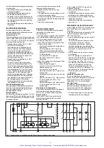
Gerät nur wie in den Abbildungen
(Fig. 2-7) beschrieben anschließen!
4. Reset the fuse: remove the short circuit
and switch off the operating voltage for
approx. 1 minute.
• Use copper wire that can withstand
60/75 °C.
• Important details in the section „Technical
Data“ should be noted and adhered to.
To operate:
• Adjust the desired delay time t1 of contact
57-58 and t2 of contact 67-68, using a
screwdriver
• Connect the supply voltage leads to
terminals A1 (-) and A2 (+)
• Closing the Feedback Control Loop
Y1 - Y2 jumpered, or connect the contacts
of external contactors/relays
• Closing the Activating Circuit
- Automatic Start: Terminals S12-S34
jumpered
- Manual Start: Replace the jumper S12-
S34 with a n/o contact of a pushbutton
• Closing the Input Circuit
- Single Channel: Terminals S21-S22 and
S12-S52 jumpered. Connect a n/c con-
tact of the activating switch to S11-S12
- Two-channel operation: no short circuit
detection: Connect n/c contacts of the
activating switch to terminals S11-S12
and S11-S52, terminals S21-S22
jumpered
- Two-channel operation, with short circuit
detection: Connect n/c contacts of the
activating switch to terminals S11-S12
and S21-S22, terminals Y36-S52
jumpered
• Closing the Reset Circuit
- w/o reset function: Jumper terminals
Y39-Y40
- with reset function: Replace the jumper
Y39-Y40 by a n/c contact
The safety contacts are activated and the
aux. contact 41-42 is open. The status
indicator LED´s illuminate. The unit is ready
for operation. If the input circuit is opened (E-
Stop Button is pressed or Safety Guard is
opened), safety contacts 13-14, 23-24 and
33-34 are opened immediately and the aux.
contact 41-42 is closed immediately. LED´s
„ch.1“ and „ch.2“ are off. The countdown of
delay time t1 and t2 is started. The safety
contact 57-58 is opened and LED t1 goes off
after delay time t1 has elapsed. The safety
contact 67-68 is opened and LED t2 goes off
after delay time t2 has elapsed.
Reactivation:
• Close input circuit
• In Manual Start mode, in addition, press
button with n/o contact between S12-S34.
The status indicators light up again, the
safety contacts are closed.
Reset
This function sets the delay time t1 and t2 to
zero. Instead of a jumper, connect a button
with n/c contact to Y39-Y40. If the contact is
opened during countdown of the delay time,
contacts 57-58 and 67-68 are opened
immediately.
The unit must only be connected as
shown in the illustrations (Fig. 2-7)!
4. Réarmement du fusible: enlever le
court-circuit et couper l‘alimentation du
relais pendant au moins 1 min.
• Utiliser uniquement des fils de câblage en
cuivre 60/75 °C.
• Respectez les données indiquées dans les
caractéristiques techniques.
Mise en oeuvre:
• Régler la temporisation t1 du contact 57-
58 et la temporisation t2 du contact 67-68
à l'aide d'un tournevis.
• Amener la tension d'alimentation aux
bornes A1 (+) et A2 (-)
• Fermer la boucle de retour:
pont entre Y1-Y2 ou câblage des
contacts externes.
• Fermer le circuit de réarmement:
- réarmement automatique: pontage des
bornes S12-S34.
- réarmement manuel: câblage d'un
poussoir sur S12-S34 (pas de
pontage).
• Fermer le circuit d'entrée:
- commande pa r 1 canal: câblage du
contact à ouverture entre S11 et S12,
pontage de S21-S22 et S12-S52
- commande par 2 canaux sans détection
de court-circuit: câblage des contacts à
ouverture entre S11-S12/S11-S52,
pontage de S21-S22
- commande par 2 canaux avec détection
de court-circuit: câblage des contacts à
ouverture entre S11-S12/S21-S22,
pontage de Y36-S52
• Fermer la boucle de Reset:
- sans fonction Reset: pont sur Y39-Y40
- avec fonction Reset: câblage d'un
contact à ouverture sur Y39-Y40.
Les contacts de sécurité sont fermés et le
contact d'information est ouvert. Les LEDs de
visualisation sont allumées. Le relais est
activé.Si le circuit d'entrée est ouvert, les
contacts de sécurité 13-14/23-24/33-34
s'ouvrent instantanément et le contact d'info
41-42 se ferme. Les LEDs "ch.1" et "ch.2"
s'éteingnent. Le contact de sécurité 57-58
s'ouvre au bout du temps t1. La LED
"t1"s'éteint. Le contact de sécurité 67-68
s'ouvre au bout du temps t2. La LED "t2"
s'éteint.
Remise en route:
• fermer le circuit d'entrée
• en cas de réarmement manuel, appuyer
sur le poussoir S12-S34.
Les affichages d'état s'allument à nouveau.
Les contacts de sécurité sont fermées.
Reset
Cette fonction permet de mettre à 0 les
temporisations t1 et t2. Pour cela un contact
à ouverture est câblé entre les bornes
Y39-Y40 à la place du pont. Si ce contact est
ouvert pendant l'écoulement des tempo-
risations, les contacts temporisés de sécurité
57-58 et 67-68 s'ouvrent instantanément.
Les exemples de branchement (Fig. 2-7)
doivent être respectés.
Artisan Technology Group - Quality Instrumentation ... Guaranteed | (888) 88-SOURCE | www.artisantg.com


