
- 2 -
• Das AC-Gerät hat einen kurzschluss-
festen Netztransformator, das DC-Gerät
eine elektronische Sicherung.
Funktionsbeschreibung
Das Schaltgerät PNOZ X4 dient dem
sicherheitsgerichteten Unterbrechen eines
Sicherheitsstromkreises. Nach Anlegen der
Versorgungsspannung leuchtet die LED
"Power". Das Gerät ist betriebsbereit, wenn der
Startkreis S33-S34 geschlossen wird (auto-
matischer Start) oder geschlossen und wieder
geöffnet wird (manueller Start).
• Eingangskreis geschlossen (z. B. Not-
Halt-Taster nicht betätigt):
Relais K1 und K2 gehen in Wirkstellung und
halten sich selbst. Die Statusanzeige "CH.
1" und "CH. 2" für Kanal 1 und 2 leuchtet.
Die Sicherheitskontakte 13-14, 23-24, 33-34
sind geschlossen, der Hilfskontakt 41-42 ist
geöffnet.
• Eingangskreis wird geöffnet (z. B. Not-
Halt-Taster betätigt):
Relais K1 und K2 fallen in die Ruhe-
stellung zurück. Die Statusanzeige "CH.
1" und "CH. 2" erlischt. Die Sicherheits-
kontakte 13-14, 23-24, 33-34 werden
redundant geöffnet, der Hilfskontakt 41-
42 geschlossen.
Function Description
The PNOZ X4 relay provides a safety-
oriented interruption of a safety circuit. When
the operating voltage is applied the LED
"Power" is illuminated. The unit is ready for
operation, when the reset circuit S33-S34 is
closed (automatic reset) or is closed and
opened again (manual reset).
• Input circuit closed (e.g. the emergency
stop button is not pressed):
Relays K1and K2 energise and retain
themselves. The status indicators "CH. 1"
and "CH. 2" for channels 1 and 2, resp.
illuminate. The safety contacts 13-14, 23-
24, 33-34 are closed, the auxiliary contact
41-42 is open.
• Input circuit is opened (e.g. emergency
stop is pressed)
Relays K1 and K2 de-energise. The status
indicators "CH.1" and "CH.2" go out. The
safety contacts 13-14, 23-24, 33-34 open
(redundantly) and the auxiliary contact 41-
42 closes.
Description du fonctionnement
Le relais PNOZ X4 assure de façon sure,
l’ouverture d’un circuit de sécurité. A la mise
sous tension du relais (A1-A2), la LED
"Power" s'allume. Le relais est activé si le
circuit de réarmement S33-S34 est fermé
(réarmement automatique) ou fermé puis
réouvert (réarmement manuel).
• Circuits d'entrée fermés (poussoir AU non
actionné) :
Les relais K1 et K2 passent en position
travail et s'auto-maintiennent. Les LEDs
"CH.1" et "CH.2" (canal 1 et canal 2)
s'allument. Les contacts de sécurité (13-
14, 23-24, 33-34) sont fermés et le
contact d'info. (41-42) est ouvert.
• Circuits d'entrée ouverts (poussoir AU
actionné) :
Les relais K1 et K2 retombent. Les LEDs
"CH.1" et "CH.2" s'éteingnent. Les
contacts de sécurité (13-14, 23-24, 33-
34) s'ouvrent et le contact d'info. (41-42)
se ferme.
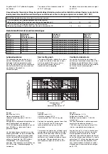
* Insulation between the non-marked area
and the relay contacts: Basic insulation
(overvoltage category III), safe separation
(overvoltage category II)
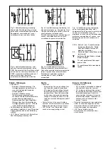
Operating Modes
• Single-channel operation: Input wiring
according to VDE 0113 and EN 60204 and
no redundancy in the input circuit. Earth
faults are detected in the emergency stop
circuit.
• Two-channel operation: no short circuit
detection: Redundant input circuit. Earth
faults and short circuits in the emergency
stop circuit are detected.
• Dual-channel operation, with short circuit
detection: Redundant input circuit. Earth
faults
in the emergency stop circuit and
shorts across the Emergency Stop push
button are also detected.
• Automatic reset: The unit is active as soon
as the input circuit is closed.
• Manual reset: The unit is active when the
reset circuit S33-S34 is closed.
• Monitored manual reset: Unit will only be
active if the reset circuit is opened before
the input circuit closes, and the reset
circuit is closed after the input circuit has
closed and the waiting period has elapsed
(see technical data). This eliminates the
possibility of the reset button being
* Isolation zum nicht markierten Bereich und der
Relaiskontakte zueinander: Basisisolierung
(Überspannungskategorie III), sichere
Trennung (Überspannungskategorie II)
Betriebsarten
• Einkanaliger Betrieb: Eingangsbeschal-
tung nach VDE 0113 und EN 60204, keine
Redundanz im Eingangskreis,
Erdschlüsse im Tasterkreis werden
erkannt.
• Zweikanaliger Betrieb ohne Querschluss-
erkennung: Redundanter Eingangskreis,
Kurzschlüsse und Erdschlüsse im
Tasterkreis werden erkannt.
• Zweikanaliger Betrieb mit Querschluss-
erkennung: Redundanter Eingangskreis,
Kurzschlüsse und Erdschlüsse im
Tasterkreis und Querschlüsse zwischen
den Tasterkontakten werden erkannt.
• Automatischer Start: Gerät ist aktiv,
sobald der Eingangskreis geschlossen ist.
• Manueller Start: Gerät ist aktiv, wenn der
Startkreis S33-S34 geschlossen wird.
• Manueller Start, überwacht: Gerät ist nur
aktiv, wenn vor dem Schließen des
Eingangskreises der Startkreis geöffnet
wird und der Startkreis nach dem Schlie-
ßen des Eingangskreises und nach Ablauf
der Wartezeit (s. techn. Daten) geschlos-
sen wird. Dadurch ist eine automatische
* Isolation de la partie non sélectionnée par
rapport aux contacts relais : isolation basique
(catégorie de surtensions III), isolation
galvanique (catégorie de surtensions II)
Modes de fonctionnement
• Commande par 1 canal : conforme aux
prescriptions de la EN 60204, pas de
redondance dans le circuit d’entrée. La mise
à la terre du circuit d’entrée est détectée
• Commande par 2 canaux sans détection de
court-circuit.: circuit d’entrée redondant. La
mise à la terre et les défaillances des
contacts sont détectées.
• Commande par 2 canaux avec détection de
court-circuit.: circuit d’entrée redondant. La
mise à la terre,les défaillance des contacts
ainsi que les courts-cirucits entre les canaux
sont détectés.
• Réarmement automatique : le relais est
activé dès la fermeture des canaux d’entrée.
• Réarmement manuel : l'appareil est activé
dès que le circuit S33-S34 est fermé.
• Réarmement manuel auto-contrôlé :
L’appareil est uniquement actif lorsque le
circuit de réarmement est ouvert avant
fermeture des circuits d’entrées et que le
circuit de réarmement est fermé après
fermeture des circuits d’entrées et
écoulement du temps d’attente (cf.
caractéristiques techniques). Cette
mesure permet d’éviter toute activation
• The AC unit is fitted with a short-circuit
proof power transformer. The DC unit has
an electronic fuse.
• transformateur interne protégé contre les
c.c pour l'alimentation en AC, fusible
électronique pour l'alimentation DC
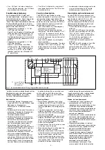
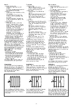
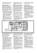
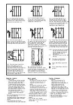
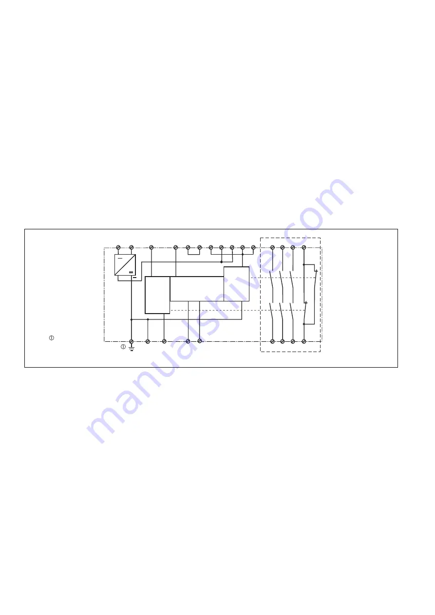
Fig. 1: Innenschaltbild/Internal Wiring Diagram/Schéma de principe
A1
A2
S34
Y1
S11
S22
Y2
41
42
S33
Y36
S12
S11
13
33
14
34
K1
K2
23
24
Kanal/
Channel/
Canal
1
Kanal/
Channel/
Canal
2
Startkreis/
Reset ciurcuit/
Circuit de
réarmement
S52
UB
S12
S21
Y37
nur am AC-Gerät/
On AC units only/
AC seulement
~
+
*