21 394-03
PNOZ s2
- 1 -
4
D
Betriebsanleitung
4
GB Operating instructions
4
F
Manuel d'utilisation
4
E
Instrucciones de uso
4
I
Istruzioni per l`uso
4
NL Gebruiksaanwijzing
21 394-03
PNOZ s2
Sicherheitsschaltgerät PNOZ s2
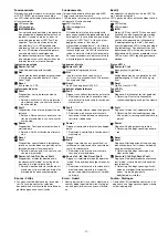
Das Sicherheitsschaltgerät dient dem sicher-
heitsgerichteten Unterbrechen eines Sicher-
heitsstromkreises.
Das Sicherheitsschaltgerät erfüllt Forderungen
der EN 60947-5-1, EN 60204-1 und VDE 0113-
1 und darf eingesetzt werden in Anwendungen
mit
`
NOT-AUS-Tastern
`
Schutztüren
PNOZ s2 safety relay
The safety relay provides a safety-related inter-
ruption of a safety circuit.
The safety relay meets the requirements of
EN 60947-5-1, EN 60204-1 and VDE 0113-1
and may be used in applications with
`
E-STOP pushbuttons
`
Safety gates
Bloc logique de sécurité PNOZ s2
Le bloc logique de sécurité sert à interrompre
en toute sécurité un circuit de sécurité.
Le bloc logique de sécurité satisfait aux exigen-
ces des normes EN 60947-5-1, EN 60204-1 et
VDE 0113-1 et peut être utilisé dans des appli-
cations avec des
`
poussoirs d'arrêt d'urgence
`
protecteurs mobiles
Zu Ihrer Sicherheit
`
Installieren und nehmen Sie das Gerät nur
dann in Betrieb, wenn Sie diese Betriebsan-
leitung gelesen und verstanden haben und
Sie mit den geltenden Vorschriften über Ar-
beitssicherheit und Unfallverhütung vertraut
sind.
Beachten Sie die VDE- sowie die örtlichen
Vorschriften, insbesondere hinsichtlich
Schutzmaßnahmen
`
Durch Öffnen des Gehäuses oder eigen-
mächtige Umbauten erlischt jegliche Ge-
währleistung.
For your safety
`
Only install and commission the unit if you
have read and understood these operating
instructions and are familiar with the applica-
ble regulations for health and safety at work
and accident prevention.
Ensure VDE and local regulations are met,
especially those relating to safety.
`
Any guarantee is rendered invalid if the hous-
ing is opened or unauthorised modifications
are carried out.
Pour votre sécurité
`
Vous n'installerez l'appareil et ne le mettrez
en service qu'après avoir lu et compris le
présent manuel d'utilisation et vous être fa-
miliarisé avec les prescriptions en vigueur
sur la sécurité du travail et la prévention des
accidents.
Respectez les normes locales ou VDE, parti-
culièrement en ce qui concerne la sécurité.
`
L'ouverture de l'appareil ou sa modification
annule automatiquement la garantie.
Gerätemerkmale
`
Relaisausgänge zwangsgeführt:
– 3 Sicherheitskontakte (S) unverzögert
– 1 Hilfskontakt (Ö) unverzögert
`
Sichere Trennung der Sicherheitskontakte
von allen anderen Stromkreisen
`
1 Halbleiterausgang
`
Anschlussmöglichkeiten für:
– NOT-AUS-Taster
– Schutztürgrenztaster
– Starttaster
`
1 Kontakterweiterungsblock PNOZsigma
über Verbindungsstecker anschließbar
`
Betriebsarten mit Drehschalter einstellbar
`
LED-Anzeige für:
`
Versorgungsspannung
`
Eingangszustand Kanal 1
`
Eingangszustand Kanal 2
`
Schaltzustand Sicherheitskontakte
`
Startkreis
`
Fehler
`
steckbare Anschlussklemmen (wahlweise
Federkraftklemme oder Schraubklemme)
Unit features
`
Positive-guided relay outputs:
– 3 safety contacts (N/O), instantaneous
– 1 auxiliary contact (N/C), instantaneous
`
Safe separation of safety contacts from all
other circuits
`
1 semiconductor output
`
Connection options for:
– E-STOP pushbutton
– Safety gate limit switch
– Reset button
`
A connector can be used to connect 1
PNOZsigma contact expander module
`
Operating modes can be set via rotary switch
`
LED indicator for:
`
Supply voltage
`
Input status, channel 1
`
Input status, channel 2
`
Switch status, safety contacts
`
Reset circuit
`
Error
`
Plug-in connection terminals (either spring-
loaded terminal or screw terminal)
Caractéristiques de l'appareil
`
Sorties de relais à contact lié :
– 3 contacts de sécurité (F) instantanés
– 1 contact d'information (O) instantané
`
Séparation galvanique entre les contacts de
sécurité de tous les autres circuits
`
1 sortie statique
`
Raccordements possibles pour :
– poussoir d'arrêt d'urgence
– interrupteur de position
– poussoir de réarmement
`
1 bloc d'extension de contacts PNOZsigma
raccordable par connecteur
`
Modes de fonctionnement réglables par sé-
lecteur
`
LED de visualisation pour :
`
tension d'alimentation
`
Etat d'entrée canal 1
`
Etat d'entrée canal 2
`
Etat de commutation des contacts de sécu-
rité
`
circuit de réarmement
`
Erreur
`
Borniers débrochables (au choix avec rac-
cordement à ressort ou à vis)
Sicherheitseigenschaften
Das Schaltgerät erfüllt folgende Sicherheitsan-
forderungen:
`
Die Schaltung ist redundant mit Selbstüber-
wachung aufgebaut.
`
Die Sicherheitseinrichtung bleibt auch bei
Ausfall eines Bauteils wirksam.
`
Bei jedem Ein-Aus-Zyklus der Maschine wird
automatisch überprüft, ob die Relais der Si-
cherheitseinrichtung richtig öffnen und
schließen.
`
Das Gerät hat eine elektronische Sicherung.
Safety features
The relay meets the following safety require-
ments:
`
The circuit is redundant with built-in self-
monitoring.
`
The safety function remains effective in the
case of a component failure.
`
The correct opening and closing of the safety
function relays is tested automatically in
each on-off cycle.
`
The unit has an electronic fuse.
Caractéristiques de sécurité
Le relais satisfait aux exigences de sécurité
suivantes :
`
La conception interne est redondante avec
une autosurveillance.
`
Le dispositif de sécurité reste actif, même en
cas de défaillance d'un composant.
`
L'ouverture et la fermeture correctes des re-
lais internes sont contrôlées automatique-
ment à chaque cycle marche/arrêt de la
machine.
`
L'appareil est équipé d'une sécurité électro-
nique.


