- 2 -
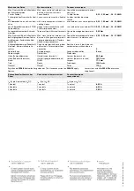
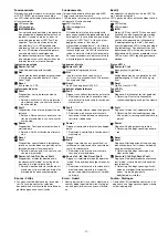
Blockschaltbild/Klemmenbelegung
Block diagram/terminal configuration
Schéma de principe/affectation des
bornes
*Sichere Trennung nach EN 60947-1, 6 kV
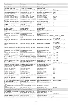
Mitte: Frontansicht mit Abdeckung
Rechts: Frontansicht ohne Abdeckung
*Safe separation in accordance with EN 60947-
1, 6 kV
Centre: Front view with cover
Right: Front view without cover
* Séparation galvanique selon la norme
EN 60947-1, 6 kV
Schéma du milieu : vue frontale avec capot de
protection
A droite : vue frontale sans capot de protection
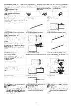
Funktionsbeschreibung
`
Einkanaliger Betrieb: keine Redundanz im
Eingangskreis, Erdschlüsse im Start- und
Eingangskreis werden erkannt.
`
Automatischer Start: Gerät wird aktiv,
nachdem Eingangskreis geschlossen
wurde.
`
Manueller Start: Gerät wird aktiv, wenn
der Eingangskreis geschlossen ist und
danach der Startkreis geschlossen wird.
`
Überwachter Start mit steigender Flanke:
Gerät wird aktiv, wenn der Eingangskreis
geschlossen ist und nach Ablauf der
Wartezeit (s. techn. Daten) der Startkreis
geschlossen wird.
`
Überwachter Start mit fallender Flanke:
Gerät wird aktiv, wenn
– der Eingangskreis geschlossen ist und
danach der Startkreis geschlossen
und wieder geöffnet wird.
– der Startkreis geschlossen und nach
Schließen des Eingangskreises wieder
geöffnet wird.
`
Kontaktvervielfältigung und –verstärkung der
unverzögerten Sicherheitskontakte durch
Verdrahtung von Kontakterweiterungs-
blöcken oder externen Schützen möglich;
1 Kontakterweiterungsblock PNOZsigma
über Verbindungsstecker anschließbar.
Function description
`
Single-channel operation: no redundancy in
the input circuit, earth faults in the reset and
input circuit are detected.
`
Automatic reset: Unit is active once the
input circuit has been closed.
`
Manual reset: Unit is active once the in-
put circuit is closed and then the reset
circuit is closed.
`
Monitored reset with rising edge: Unit is
active once the input circuit is closed and
once the reset circuit is closed after the
waiting period has elapsed
(see technical details).
`
Monitored reset with falling edge: Unit is
active once
– the input circuit is closed and then the
reset circuit is closed and opened
again.
– the reset circuit is closed and then
opened again once the input circuit is
closed.
`
Increase in the number of available instanta-
neous safety contacts by connecting contact
expander modules or external contactors/re-
lays;
A connector can be used to connect 1
PNOZsigma contact expander module.
Description du fonctionnement
`
Commande par 1 canal : pas de redondance
dans le circuit d'entrée, les mises à la terre
dans les circuits de réarmement et d'entrée
sont détectées.
`
Réarmement automatique : l'appareil est
activé une fois que le circuit d'entrée est
fermé.
`
Réarmement manuel : l'appareil est acti-
vé lorsque le circuit d'entrée est fermé et
après que le circuit de réarmement se
soit fermé.
`
Réarmement auto-contrôlé avec front
montant : l'appareil est activé lorsque le
circuit d'entrée est fermé et lorsque le
circuit de réarmement se ferme après
l'écoulement du temps d'attente (voir les
caractéristiques techniques).
`
Réarmement auto-contrôlé avec front
descendant : l'appareil est actif si
– le circuit d'entrée est fermé puis le cir-
cuit de réarmement fermé et réouvert.
– le circuit de réarmement est fermé
puis réouvert après la fermeture du cir-
cuit d'entrée.
`
Augmentation et renforcement possibles du
nombre de contacts de sécurité instantanés
par le câblage des blocs d'extension des
contacts ou de contacteurs externes ;
1 bloc d'extension de contacts PNOZsigma
raccordable par connecteur.
Input
A1 A2
=
Power
Reset/
Start
S34
=
Y32
K1
K2
13 23 33 41
24 34 42
14
Interface expansion
unit
*


