Supplementary data
Operating Manual PSSu K F EI
1003303-EN-03
| 69
9.1.8.2
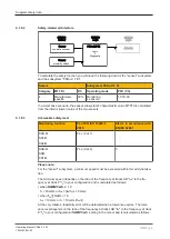
Safety-related architecture
SRP/CS
Sensor
Sensor
non-safe encoder
Logic
+
Diagnostic
Actuator
PSSu K F EI
SRP/CS
Logic
SRP/CS
Logic
Sensor
proximity switch
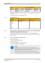
To calculate the safety function you will need the following data for the "sensor" subsystem
and the subsystem "PSSu K F EI":
Sensor
Subsystem PSSu K F EI
Category
MTTFd
DC
Operating mode
PFH (1/h)
4
Manufacturer-
specific
90 %
Monitoring
2 sensors
1,01E-09
In a worst case scenario, the sensor subsystem's characteristic value MTTFd is calculated
from the inferior (lower) value of the two sensors.
9.1.8.3
Achievable safety level
Monitoring function
PL of EN ISO 13849-1:
2015
SIL CL in accordance with
EN IEC 62061
SOS-M
SDI-M
SS2-M
PL c (Cat.1)
-
SSR-M
SSM
SS1-M
PL e (Cat.4)
3
Please note:
For the "sensor" subsystem, a minimum speed must be exceeded within forced dynamisa-
tion.
The minimum speed depends on the ratio of the frequency at tracks AB "
f
AB
" to the fre-
quency at track Z "
f
Z
" in your configuration and is calculated as follows:
}
when
fAB/fZ Verh.
≥ 1.0
f
Z
= 10 mHz or
f
AB
= (
f
AB
/f
Z
)
x
10 mHz
}
when
f
AB
/f
Z
Verh.
< 1.0
f
AB
= 10 mHz or
f
Z
= 10 mHz/(
f
AB
/
f
z
)
At the very latest, a feasibility error will be detected when a tolerance expires. The toler-
ance level depends on the ratio of the frequency at tracks AB "
f
AB
" to the frequency at track
Z "
f
Z
" in your configuration (
fAB/fZ Verh.
setting in the menu) and is calculated as follows:


