Wiring
Operating Manual PSSu K F EI
1003303-EN-03
| 46
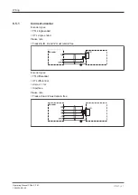
pnp proximity switch with resistor R = 10 kOhm
1
2
5
4
Ini A
Ini B
0 V
S
X 31
X 32
4
5
7
8
3
6
2
1
npn proximity switch with resistor R = 47 kOhm
Ini A
Ini B
0 V
S
1
2
5
4
X 31
X 32
4
5
7
8
3
6
2
1
6.5
Connection of encoders
Connector pin assignment X31, depending on the technology
Mini-IO socket
8-pin
PIN
HTL/TTL
Sin/Cos
Hiperface
8 6 4 2
7 5 3 1
1
S (optional)
S (optional)
S (optional)
2
GND
GND
GND
3
Z
Z or index
4
A
Sin
Sin
5
/A
-Sin
RefSin
6
/Z
Z or index
7
B
Cos
Cos
8
/B
-Cos
RefCos
Proceed as follows when connecting the encoder:
}
Use only shielded cables for all connections. Please refer to the chapter
.
}
Always connect GND on the encoder to GND on the Mini-IO socket.


