Function description
Operating Manual PSEN ml s 1.1/2.1/2.2
1004710-EN-05
| 13
4
Function description
4.1
Structure
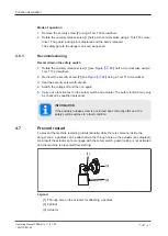
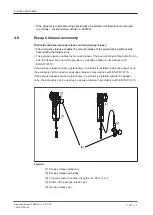
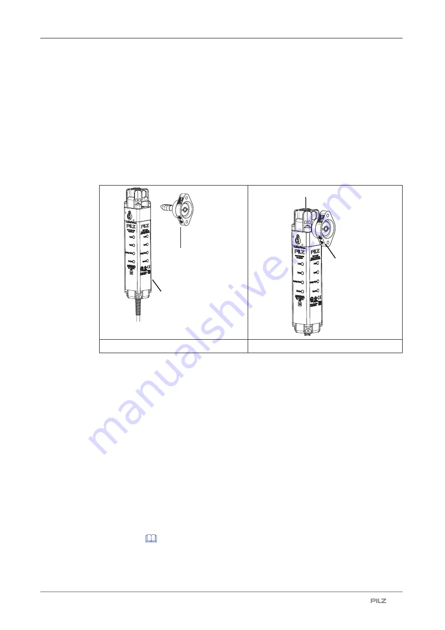
The interlocking and guard locking system prevents the safety gates to the danger zone
from being opened while there is any hazard within the danger zone (machine movement,
voltage, ...).
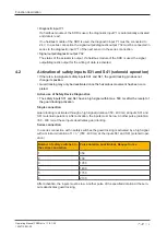
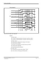
The safety outputs may have a high or low signal, depending on the position of the actuator
and the signal path of safety inputs S31 and S41 (solenoid operation).
Safety switch
Actuator
Safety switch
Actuator
Gate open
Gate closed
Safety outputs 12 and 22
Under these conditions there is a high signal at safety outputs 12 and 22:
}
Actuator is detected
and
}
Guard locking pin has successfully been activated (guard locking pin is in the locked posi-
tion)
and
}
There is a high signal at the inputs S11 and S21
If one of these conditions is not met, the signal at the safety outputs will be low.
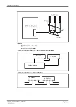
Plausibility monitoring for safety inputs S11 and S21
}
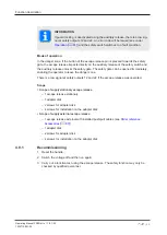
If one safety input switches from high to low, while the other safety input remains high, an
unequal status is displayed:
Input LED flashes yellow
}
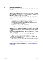
If this safety input switches back from low to high, while the other safety input remains
high, a plausibility error is displayed and a partial operation lock is triggered:
Input LED
flashes yellow
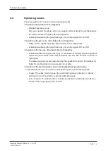
A switch to a high signal will only lead to normal safety switch operation if both inputs had a
low signal. From this moment on, the switch to high may occur (partial operation lock see
).


