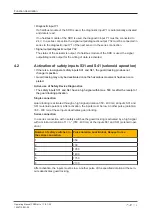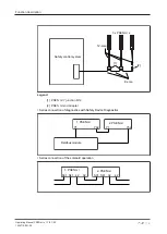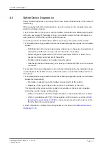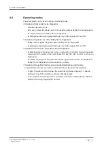
Function description
Operating Manual PSEN ml s 1.1/2.1/2.2
1004710-EN-05
| 23
Mode of operation
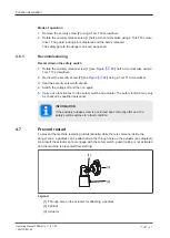
1. Remove the security screw [2] using a Torx T10 screwdriver.
2. Rotate the auxiliary release screw [1] half a turn anti-clockwise using a Torx T10 screw-
driver. The guard locking pin is displaced and the bolt is released.
The safety gate to the danger zone can be opened.
4.6.1
Recommissioning
Recommission the safety switch
1. Rotate the auxiliary release screw [1] (see
Figure [
) half a turn clockwise using a
Torx T10 screwdriver.
2. Re-insert the security screw [2] (see
Figure [
) using a Torx T10 screwdriver.
3. Seal the security screw with varnish.
4. Switch the voltage off and then on again.
5. Carry out a function test on the safety switch and actuator. The safety function may only
be checked by qualified personnel.
INFORMATION
If the auxiliary release screw is not turned back correctly after use, the
safety switch switches to a fault condition.
4.7
Prevent restart
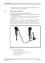
To prevent the machine restarting (unintentionally) while there is someone inside the
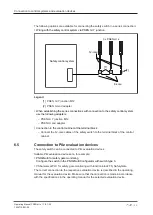
danger zone, a padlock can be attached via the through hole on the actuator (see diagram).
As a result the actuator cannot engage with the safety switch, guard locking is not activated
and the machine is prevented from starting.
[1]
[2]
[3]
Legend
[1] Through hole on the actuator for attaching a padlock
[2] Padlock
[3] Actuator


