background image

Connection to control systems and evaluation devices

Operating Manual PSEN ml sa 1.1/2.1/2.2, PSEN ml DHM
1005457-EN-02

| 37

6.5

Connection to Pilz evaluation devices

The safety switch can be connected to Pilz evaluation devices.

Suitable Pilz evaluation devices are, for example:

}

PNOZmulti for safety gate monitoring
Configure the switch in the PNOZmulti Configurator with switch type 3.

}

PSSuniversal PLC for safety gate monitoring with function block FS_SafetyGate

The correct connection to the respective evaluation device is described in the operating
manual for the evaluation device. Make sure that the connection is made in accordance
with the specifications in the operating manual for the selected evaluation device.

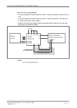
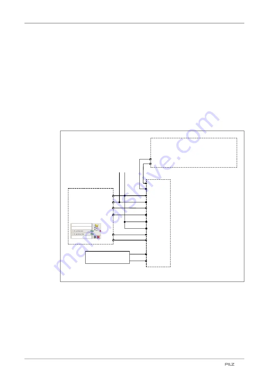
Connection to PNOZmulti is illustrated by way of example.

Connection example with PNOZmulti and Safety Device Diagnostics

A1

A2

I0

I1

A1

A2

Y32

Y1

12
22

5

1

4

6

8

3

2

9

PNOZmulti

PSEN ml

0 V

24 V

S31

S41

O2 (FS)

O1 (FS)

Rx

10

7

S11

S21

Tx

32

42

11

12

Activation of guard locking via SDD ES module

following PSEN ml

Summary of Contents for 570430

Page 1: ...PSEN ml sa 1 1 2 1 2 2 PSEN ml DHM Operating Manual 1005457 EN 02 PSEN sensor technology ...

Page 2: ...enta tion will be gratefully received Source code from third party manufacturers or open source software has been used for some components The relevant licence information is available on the Internet on the Pilz homepage Pilz PIT PMI PNOZ Primo PSEN PSS PVIS SafetyBUS p SafetyEYE SafetyNET p the spirit of safety are registered and protected trademarks of Pilz GmbH Co KG in some countries SD means...

Page 3: ...puts S31 and S41 solenoid operation 14 4 2 1 Activation with specification of direction 16 4 2 2 Activation without specification of direction 16 4 3 Safety Device Diagnostics 17 4 4 Operating modes 17 4 5 Block diagram 21 4 6 Auxiliary release 22 4 6 1 Recommissioning 22 4 7 Prevent restart 23 4 8 Escape release 23 4 8 1 Recommissioning 23 4 9 Accessories escape release 24 4 9 1 Recommissioning 2...

Page 4: ...ory 47 8 4 1 Important information 47 8 4 2 Installation positions for escape release 48 8 4 3 Installation stationary escape release 48 9 Adjustment 51 9 1 Attach safety switch and actuator 51 10 Operation 52 10 1 Normal operation mlock 52 10 2 Error display 55 11 Checks and maintenance 56 12 Dimensions 58 13 Technical details for safety switch 62 14 Technical details for actuator order no 6O0000...

Page 5: ...Contents Operating Manual PSEN ml sa 1 1 2 1 2 2 PSEN ml DHM 1005457 EN 02 5 21 Appendix 77 22 EC declaration of conformity 78 ...

Page 6: ...mbols Information that is particularly important is identified as follows DANGER This warning must be heeded It warns of a hazardous situation that poses an immediate threat of serious injury and death and indicates preventive measures that can be taken WARNING This warning must be heeded It warns of a hazardous situation that could lead to serious injury and death and indicates preventive measure...

Page 7: ...Introduction Operating Manual PSEN ml sa 1 1 2 1 2 2 PSEN ml DHM 1005457 EN 02 7 INFORMATION This gives advice on applications and provides information on special fea tures ...

Page 8: ...ditions There is a high signal at safety outputs 12 and 22 and There is a low signal at safety outputs S31 Lock Unlock Request 1 and S41 Lock Un lock Request 2 Safety inputs S31 and S41 solenoid operation may only be operated under the following condition Plant is in a safe condition Make sure that this is the case with an AND operation in the safety system immediately before the output is operate...

Page 9: ...safety assessment in accordance with the Machinery Directive is required The product as an individual component fulfils the functional safety requirements in accord ance with EN ISO 13849 and EN 62061 However this does not guarantee the functional safety of the overall plant machine To achieve the relevant safety level of the overall plant machine s required safety functions each safety function n...

Page 10: ...nded Damage can be attributed to not having followed the guidelines in the manual Operating personnel are not suitably qualified Any type of modification has been made e g exchanging components on the PCB boards soldering work etc 2 2 5 Disposal In safety related applications please comply with the mission time TM in the safety related characteristic data When decommissioning please comply with lo...

Page 11: ...N ml DHM down l 1 1 PSEN ml DHM down r 1 1 PSEN ml sa 2 X Safety switch Actuator PSEN ml sa 2 1 switch PSEN ml DHM up l 2 1 PSEN ml DHM up r 2 1 PSEN ml DHM down l 2 1 PSEN ml DHM down r 2 1 PSEN ml sa 2 2 switch PSEN ml DHM up l 2 1 PSEN ml DHM up r 2 1 PSEN ml DHM down l 2 1 PSEN ml DHM down r 2 1 The available actuators are combined in this document as follows Product type Designation in this d...

Page 12: ...ut for Y1 for Safety Device Diagnostics SDD Signal output diagnostic output Y32 for Safety Device Diagnostics Monitoring of shorts between the safety outputs Guard locking element keeps the safety gate from being opened unintentionally Auxiliary release for opening the safety gate 1 signal output Suitable for left and right hinged safety gates Pilz coding type PSEN ml sa 1 1 coded PSEN ml sa 2 1 f...

Page 13: ...r these conditions there is a high signal at safety outputs 12 and 22 Actuator is detected and Guard locking pin has successfully been activated guard locking pin is in the locked posi tion and There is a high signal at the inputs S11 and S21 If one of these conditions is not met the signal at the safety outputs will be low Plausibility monitoring for safety inputs S11 and S21 If one safety input ...

Page 14: ...nputs S31 and S41 solenoid operation If there is a low signal at safety inputs S31 and S41 the guard locking pin does not change its position Guard locking may only be deactivated once the hazardous movement has been com pleted Active use of Safety Device Diagnostics The safety inputs S31 and S41 have a high signal within max 500 ms after the receipt of the guard locking activation Single connecti...

Page 15: ...X1 X2 X3 X1 X2 Safety control system 8 core 12 core 1 2 Legend 1 PSEN ml Y junction M12 2 PSEN ml end adapter Series connection of diagnostics with Safety Device Diagnostics Y1 Y32 Y1 Y32 1 PSEN ml 2 PSEN ml Fieldbus module Series connection of the solenoid operation S31 S41 42 32 S31 S41 32 42 1 PSEN ml 2 PSEN ml ...

Page 16: ...edges from S31 to S41 is between 40 ms and 500 ms S31 before S41 The guard locking is deactivated when the time between the rising edges from S31 to S41 is between 40 ms and 500 ms S41 before S31 S31 S41 tmax Guard locking S31 S41 tmax Guard locking Activation Deactivation Legend tmax Maximum time between the rising edges from S31 and S42 4 2 2 Activation without specification of direction The gua...

Page 17: ...ithin a series connection The results of the sensor diagnostics can be checked already during the installation phase via the display in the fieldbus module without the need to connect the fieldbus module to the network With Safety Device Diagnostics there are the following diagnostic options for the fieldbus module for simple wiring Information is passed on via the fieldbus module directly to the ...

Page 18: ...and and the status of the safety inputs S31 and S41 S31 and S41 must have a high signal The safety requirements are guaranteed by the signals S31 and S41 the fieldbus for Safety Device Diagnostics communication is not safe Operation with specified direction when activating deactivating guard locking A specified direction can be used to control switching of the guard locking status Toggle The safet...

Page 19: ...he door connected upstream in the series connection is closed 3 The door connected upstream in the series connection is locked 4 Gate is closed 5 Guard locking is activated by the safety control system 6 Guard locking is activated 7 Execution of the hazardous machine function is permitted 8 Outputs will be deactivated 9 Guard locking will be deactivated 10 Gate is open t1 Processing time of guard ...

Page 20: ...tream in the series connection is closed 3 The door connected upstream in the series connection is locked 4 Gate is closed 5 Guard locking is activated by the programmable safety system 6 Guard locking is activated 7 Execution of the hazardous machine function is permitted 8 Outputs will be deactivated 9 Guard locking will be deactivated 10 Gate is open t1 Processing time of guard locking signal 1...

Page 21: ...g Manual PSEN ml sa 1 1 2 1 2 2 PSEN ml DHM 1005457 EN 02 21 4 5 Block diagram Actuator A1 A2 12 22 S31 S41 UB Device Receiver Safety Gate Magnet Lock Power Y32 Lock Sensor 1 Lock Sensor 2 Y1 S11 S21 32 42 Signal Diagnostic Output ...

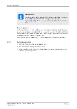
Page 22: ...ard locking pin is displaced and the bolt is released The safety gate to the danger zone can be opened INFORMATION If guard locking is deactivated using the auxiliary release there is a low sig nal at safety outputs 12 and 22 A warning will be output see chapter Operation 52 The safety switch does not switch to the fault condi tion It is possible to open the guard locking using the control system ...

Page 23: ...agram As a result the ac tuator cannot engage with the safety switch guard locking is not activated and the machine is prevented from starting Minimum 2 maximum 6 padlocks Padlock bow diameter 6 mm with maximum 6 padlocks 7 mm with maximum 3 padlocks 2 3 1 Legend 1 Actuator PSEN ml DHM 2 Flap on the actuator PSEN ml DHM for attaching the padlocks 3 Padlock 4 8 Escape release The actuator PSEN ml D...

Page 24: ...safety function may only be checked by qualified personnel 4 9 Accessories escape release If the escape release accessory order no 570460 is installed outside the danger zone the accessory can be used as an emergency release in accordance with EN ISO 14119 NOTICE For an emergency release use PSEN ml s 1 1 2 1 2 2 with the accessory escape release ...

Page 25: ...Function description Operating Manual PSEN ml sa 1 1 2 1 2 2 PSEN ml DHM 1005457 EN 02 25 1 2 3 Legend 1 Escape release stationary 2 Button of the escape release pin 3 Escape release pin ...

Page 26: ...se pin is pressed towards the safety gate the escape release impacts directly on the auxiliary release of the safety switch and the auxiliary release unlocks the safety gate The safety gate can be opened immediately enabling the operator to leave the danger zone There is a low signal at safety outputs 12 and 22 if the escape release was operated 4 9 1 Recommissioning 1 Pull back the button of the ...

Page 27: ...nment connector and cable NOTICE The colour marking for the connection lead only applies for the cable that Pilz supplies as an accessory 12 pin M12 male connector PIN Function Terminal designation Cable colour Pilz cable 1 24 V UB A1 Brown 2 0 V UB A2 Blue 3 Operation of solenoid to open and close guard lock ing channel 2 S41 White 4 Safety output channel 1 12 Green 5 Operation of solenoid to ope...

Page 28: ... wiring and EMC requirements of EN 60204 1 are met UL requirement The supply voltage to the safety switch must be protected with a quick acting fuse see Technical details 62 The inputs and outputs of the safety switch must have a protective separation to voltages over 60 VDC The power supply must meet the regulations for extra low voltages with protective elec trical separation SELV PELV INFORMATI...

Page 29: ...locked before both return to the Gate locked state and vice versa OSSD signals are evaluated through 2 channels The state of the OSSDs must be tested before and after safety inputs S31 and S41 are activated solenoid operation see Timing diagram 19 The use of Safety Device Diagnostics is described in the System Description Safety Device Diagnostics WARNING Risk of injury due to loss of the safety f...

Page 30: ...ve 2 channel operation via safe out puts which are suitable for PL e Cat 4 applications 2 channel operation for safety inputs S31 and S41 solenoid operation each with 0 5 A 2 channel processing of safety outputs Monitoring of shorts across signal cables through activation of guard locking A1 A2 22 S31 S41 12 24 V 0 V Lock Unlock Request 2 Lock Unlock Request 1 S11 S21 Safety control system Activat...

Page 31: ...2 channel operation for safety inputs S31 and S41 solenoid operation each with 0 5 A 2 channel processing of safety outputs Exclusion of shorts across signal cables through appropriate measures e g protected cable layout see EN ISO 13849 2 22 S31 S41 12 Lock Unlock Request 2 Lock Unlock Request 1 24 V 1 A1 A2 24 V 0 V S11 S21 Safety control system Activation of guard locking PSEN ml actuator PSEN ...

Page 32: ...rocessing of safety outputs 1 channel operation for interconnected safety inputs S31 and S41 solenoid operation with 1 A 22 S31 S41 12 Lock Unlock Request A1 A2 24 V 0 V S11 S21 Safety control system Activation of guard locking PSEN ml actuator PSEN ml safety switch 6 3 Single connection 24 V 0 V A1 A2 12 22 I2 FS I1 FS FS Failsafe A1 A2 S31 S41 Y32 O2 FS O1 FS I1 Y1 24 V Actuator Safety switch Pr...
Page 33: ...ce Up to 16 safety switches can be configured in series In practice the maximum possible number will be limited by the following parameters among others The required SIL level e g SIL CL 3 the required performance level e g PL e Cat 4 the maximum delay or risk time permitted by the application Cable length see notes on cable lengths Height of supply voltage Ensure there is sufficient supply voltag...

Page 34: ... m 6 5 m 5 m 5 m 5 m 5 m 5 m 30 m Supply voltage at the safety control system 24 V Number of safety switches L1 L2 L3 L4 L5 L6 Overall length 1 120 m 120 m 2 60 m 60 m 120 m 3 50 m 50 m 20 m 120 m 4 50 m 30 m 20 m 20 m 120 m 5 50 m 20 m 20 m 20 m 10 m 120 m 6 20 m 20 m 20 m 20 m 20 m 20 m 120 m Supply voltage at the safety control system 28 8 V Number of safety switches L1 L2 L3 L4 L5 L6 Overall l...

Page 35: ...41 Y32 42 32 12 22 12 22 A1 A2 A1 A2 Rx Tx S21 S11 I2 I1 S21 S11 32 42 S31 S41 42 32 S31 S41 O2 O1 Y1 Y32 Y1 Y32 Y1 Actuator Safety switch Fieldbus module Safety control system Safety switch Safety switch Actuator Actuator The following options are available for connecting the safety switch in a series connection Wiring with the safety control system via PSEN ml Y junction ...

Page 36: ...em 8 core 12 core 1 2 Legend 1 PSEN ml Y junction M12 2 PSEN ml end adapter When establishing the series connections with connection to the safety control system use the following adapters PSEN ml Y junction M12 PSEN ml end adapter Connection in the control cabinet at the terminal block Connect the 12 core cables of the safety switch to the terminal block of the control cabinet ...

Page 37: ...te monitoring with function block FS_SafetyGate The correct connection to the respective evaluation device is described in the operating manual for the evaluation device Make sure that the connection is made in accordance with the specifications in the operating manual for the selected evaluation device Connection to PNOZmulti is illustrated by way of example Connection example with PNOZmulti and ...

Page 38: ...safety switch s response range as the only transponder As soon as the actuator is detected the Safety Gate LED will flash yellow 2 After 20 s has elapsed the Safety Gate LED turns to quick yellow flashes Trigger a system reset in the next 120 s by interrupting the power supply 3 When the supply voltage is switched back on the learning procedure is complete and the number of permitted additional le...

Page 39: ...rface The safety switch and actuator should be installed opposite each other in parallel After installation at least one of the auxiliary releases escape releases must be operated Use the same type of screw to attach the safety switch and actuator Use non removable flat head locking screws to attach the safety switch and actuator e g cheese head or pan head screws or rivets For a minimum screw dep...

Page 40: ...rces arise based on the installation Installation on sliding gates Holding force FZh 2000 N Holding force F1max in accordance with EN ISO 14119 4000 N Installation on swing gates Holding force FZh 3000 N Holding force F1max in accordance with EN ISO 14119 6000 N The tapped holes must have a depth of at least 6 mm Installation of safety switch Tapped hole Fixing screws in parallel side on to actuat...

Page 41: ...d holes as indicated 1 Attach the safety switch to the swing gate sliding gate 2 Use four M5 screws to fix the safety switch to the mounting surface 8 2 2 Installation with mounting plate ø 8 5 Fixing screws in parallel side on to actu ator with mounting plate Provide the mounting surface with tapped holes as indicated 1 Attach the mounting plate to the swing gate sliding gate 2 Use four M5 screws...

Page 42: ...actuator must also be installed using a mounting plate see Install actuator on mounting plate 44 8 2 3 Install fixing screws in parallel to actuator Use four M5 screws to fix the safety switch to the mounting surface PSEN ml DHM 1 2 3 Legend 1 Safety switch 2 Actuator 3 Fixing screws of the safety switch in parallel to the respective actuator 8 2 4 Install fixing screws side on to actuator Use fou...

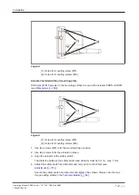
Page 43: ...tor should be installed so that the escape release handle is only accessible from inside the danger zone The escape release handle must be clearly visible and must not be concealed The PSEN ml with DHM can be installed on left and right hinged swing gates within the protected and non protected area For correct installation it s essential to comply with the distances shown in the diagram 1 2 3 Lege...

Page 44: ...l actuator on swing gate Note that washers must be used when fastening M8 screws Actuator installed on mounting plate Drill holes for M8 screws in the mounting surface to secure the PSEN ml DHM mounting plate see Dimensions 60 3 2 1 Legend 1 PSEN ml DHM mounting plate see Order reference 75 2 Holes for one way screws 3 Holes for mounting screw Actuator installed without mounting plate Drill holes ...

Page 45: ...nd secure the screw connections using a medium strength threadlocker If you need to extend the handle with the PSEN ml DHM extension use M5x45 mm or M5x70 mm fixing screws 5 Apply the grip insert to the handle Use the red PSEN ml DHM handle with red grip insert for an escape release Use the yellow PSEN ml DHM handle with yellow grip insert for other applications To bridge larger distances the rota...

Page 46: ... Legend 1 Holes for mounting screw M5 2 Holes for mounting screws M8 1 Use two screws M8 to fix the mounting flaps in place 2 Use two screws to fix the actuator in place 3 Align the actuator to the safety switch The distance between the safety switch and actuator must be 5 mm max 1 mm 4 Adjust the safety switch and actuator and carry out a function test see Adjustment 51 Secure the safety switch a...

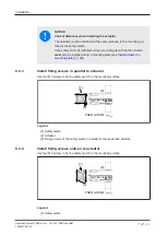
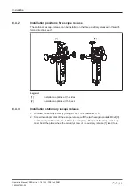
Page 47: ...e with yellow grip insert for other applications To bridge larger distances the rotary handle can be further offset by 25 mm a maximum of twice see Order reference 75 8 4 Escape release accessory 8 4 1 Important information The escape release accessory may be installed outside the danger zone as an emergency release in accordance with EN ISO 14119 Prevent any unintended operation of the escape rel...

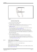
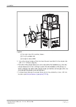
Page 48: ... each 1 2 Legend 1 Installation options at the sides 2 Installation options at the back 8 4 3 Installation stationary escape release 1 Remove the security screw 1 using a Torx T10 screwdriver T10 2 Screw the adapter disk of the escape release with the two hexagon sockets M3x8 3 on the safety switch with 1 2 1 5 Nm see diagram The pin of the adapter disk 2 must be at the place where the security sc...

Page 49: ... disk with 1 2 1 5 Nm see diagram The button of the escape release pin can be removed for the installation e g when the escape release pin is to be run through a wall Once the installation of the escape re lease is complete the button of the escape release pin must be secured again with a me dium strength threadlocker and hand tightened To bridge larger distances the escape release pin can be exte...

Page 50: ...Installation Operating Manual PSEN ml sa 1 1 2 1 2 2 PSEN ml DHM 1005457 EN 02 50 2 1 Legend 1 Button of the escape release pin 2 Escape release pin ...

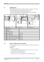
Page 51: ...ve view 1 Safety switch 2 Actuator 3 Bolt in the actuator 4 Max lateral offset 2 0 mm 5 Max vertical offset 2 0 mm 6 Max angular offset around the X axis 2 0 deg 7 Max angular offset around the Y axis 2 5 deg 8 Max angular offset around the Z axis 5 0 deg 9 Max offset in closing direction 5 0 mm 9 1 Attach safety switch and actuator Once the safety switch and actuator are correctly aligned the act...

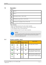
Page 52: ... locking active Input LED lights up yellow The unit is ready for operation NOTICE The safety function should be checked after initial commissioning and each time the plant machine is changed The safety functions may only be checked by qualified personnel 10 1 Normal operation mlock LED status Switch status Device Safety Gate Input Lock Green Yellow Yel low Green The safety switch is started Green ...

Page 53: ...locking cannot be activated deac tivated Check the actu ator s alignment 51 to the safety switch The supply voltage to safety inputs S31 and S41 was switched back on before the auxili ary release screw was turned back Turn back the auxiliary release screw and then switch the supply voltage on see Recommissionin g 22 Green Display not defin itive Yel low Yellow Guard locking pin is in an interme di...

Page 54: ...tion lock One input is low after both inputs were high Open both in puts This will cancel the lock Red Display not defin itive Yel low Green Partial operation lock Both inputs are high Green Display not defin itive Dis play not defin itive Red Auxiliary release escape release activated Auxiliary re lease Turn back the auxili ary release screw and then recommission the safety switch again see Recom...

Page 55: ...ult condition Check the wiring and switch the supply voltage off and then on again Red Red Auxiliary release escape release activated Auxiliary release Turn back the auxiliary release screw and then switch the supply voltage on see Recommissioning 22 Escape release Pull the button of the escape release pin back again and then switch on the sup ply voltage again see Recommis sioning under escape re...

Page 56: ... intact If the seal is not intact insert the security screw is inserted and use varnish to seal the security screw Check the safety switch and actuator for damage Check that the safety switch and actuator are firmly secured Check the offset of the safety switch and actuator Max lateral offset Max angular offset Max vertical offset Check the distance between the safety switch and actuator This dist...

Page 57: ...Checks and maintenance Operating Manual PSEN ml sa 1 1 2 1 2 2 PSEN ml DHM 1005457 EN 02 57 Check the function of the escape release ...

Page 58: ...Dimensions Operating Manual PSEN ml sa 1 1 2 1 2 2 PSEN ml DHM 1005457 EN 02 58 12 Dimensions Safety switch 31 19 2 193 5 4 5 40 31 230 ...

Page 59: ...Dimensions Operating Manual PSEN ml sa 1 1 2 1 2 2 PSEN ml DHM 1005457 EN 02 59 Actuator Fig Plan view Fig Front view ...

Page 60: ...sions Operating Manual PSEN ml sa 1 1 2 1 2 2 PSEN ml DHM 1005457 EN 02 60 Fig Side view Mounting plate see Accessories 75 255 12 5 43 25 193 5 20 4 5 31 280 12 5 n 8 5 M 5 n 8 5 M 5 10 Fig Order no 570 490 ...

Page 61: ... 1 2 1 2 2 PSEN ml DHM 1005457 EN 02 61 Mounting plate for PSEN ml DHM see Accessories 75 151 99 126 12 5 26 20 8 5 M 5 x 0 8 10 Fig Order no 6O 000 013 Dimensions of mounting flap for PSEN ml DHM 10 5 3 8 5 20 75 12 5 13 5 31 1 20 2 8 65 40 ...

Page 62: ...Hz Max transmitter output 15 mW 15 mW 15 mW Electrical data 570435 570433 570431 Supply voltage Voltage 24 V 24 V 24 V Kind DC DC DC Voltage tolerance 20 20 20 20 20 20 Output of external power supply DC 1 W 1 W 1 W Max switching frequency 1 Hz 1 Hz 1 Hz Magnet supply voltage 24 V 24 V 24 V Max solenoid current t 150 ms 1 A 1 A 1 A Max cable capacitance at the safety outputs No load PNOZ with re l...

Page 63: ...C 13 DC 13 Times 570435 570433 570431 Test pulse duration safety outputs 450 µs 450 µs 450 µs Switch on delay after UB is applied 1 1 s 1 1 s 1 1 s Inputs typ 1 ms 1 ms 1 ms Inputs max 3 ms 3 ms 3 ms Actuator typ 30 ms 30 ms 30 ms Actuator max 50 ms 50 ms 50 ms Delay on de energisation Inputs typ 3 ms 3 ms 3 ms Inputs max 5 ms 5 ms 5 ms Actuator typ 30 ms 30 ms 30 ms Actuator max 40 ms 40 ms 40 ms...

Page 64: ...8 2 6 EN 60068 2 6 EN 60068 2 6 Frequency 10 55 Hz 10 55 Hz 10 55 Hz Amplitude 1 mm 1 mm 1 mm Shock stress In accordance with the standard EN 60068 2 27 EN 60068 2 27 EN 60068 2 27 Number of shocks 3 3 3 Acceleration 30g 30g 30g Duration 11 ms 11 ms 11 ms Airgap creepage Overvoltage category III III III Pollution degree 3 3 3 Rated insulation voltage 75 V 75 V 75 V Rated impulse withstand voltage ...

Page 65: ...ainless steel plastic galvanised steel Zn Aluminium stainless steel plastic galvanised steel Zn Aluminium stainless steel plastic galvanised steel Zn Max torque setting for fix ing screws 6 6 5 Nm 6 6 5 Nm 6 6 5 Nm Max torque setting es cape release 1 2 1 5 Nm 1 2 1 5 Nm 1 2 1 5 Nm Max torque setting for mounting plate 22 24 Nm 22 24 Nm 22 24 Nm Max torque setting for mounting bracket 14 16 Nm 14 ...

Page 66: ... 2 14 EN 60068 2 14 EN 60068 2 14 EN 60068 2 14 Temperature range 0 60 C 0 60 C 0 60 C 0 60 C Storage temperature In accordance with the standard EN 60068 2 1 2 EN 60068 2 1 2 EN 60068 2 1 2 EN 60068 2 1 2 Temperature range 25 70 C 25 70 C 25 70 C 25 70 C Climatic suitability In accordance with the standard EN 60068 2 78 EN 60068 2 78 EN 60068 2 78 EN 60068 2 78 Humidity 93 r h at 40 C 93 r h at 4...

Page 67: ... 0 mm Max lateral offset 2 0 mm 2 0 mm 2 0 mm 2 0 mm Max angular offset around the X axis 2 0 deg 2 0 deg 2 0 deg 2 0 deg Max angular offset around the Y axis 2 5 deg 2 5 deg 2 5 deg 2 5 deg Max angular offset around the Z axis 5 0 deg 5 0 deg 5 0 deg 5 0 deg Max offset in closing direction 5 0 mm 5 0 mm 5 0 mm 5 0 mm Max retract speed of actuator 0 3 m s 0 3 m s 0 3 m s 0 3 m s Material Stainless...

Page 68: ... 2 14 EN 60068 2 14 EN 60068 2 14 EN 60068 2 14 Temperature range 0 60 C 0 60 C 0 60 C 0 60 C Storage temperature In accordance with the standard EN 60068 2 1 2 EN 60068 2 1 2 EN 60068 2 1 2 EN 60068 2 1 2 Temperature range 25 70 C 25 70 C 25 70 C 25 70 C Climatic suitability In accordance with the standard EN 60068 2 78 EN 60068 2 78 EN 60068 2 78 EN 60068 2 78 Humidity 93 r h at 40 C 93 r h at 4...

Page 69: ... 0 mm Max lateral offset 2 0 mm 2 0 mm 2 0 mm 2 0 mm Max angular offset around the X axis 2 0 deg 2 0 deg 2 0 deg 2 0 deg Max angular offset around the Y axis 2 5 deg 2 5 deg 2 5 deg 2 5 deg Max angular offset around the Z axis 5 0 deg 5 0 deg 5 0 deg 5 0 deg Max offset in closing direction 5 0 mm 5 0 mm 5 0 mm 5 0 mm Max retract speed of actuator 0 3 m s 0 3 m s 0 3 m s 0 3 m s Material Stainless...

Page 70: ...ing Manual PSEN ml sa 1 1 2 1 2 2 PSEN ml DHM 1005457 EN 02 70 16 Technical details for escape release 570460 General 570460 Certifications CE Mechanical data 570460 Release force escape release 80 N Service life escape release 6050 cycles Weight 115 g ...

Page 71: ...l Safety aspects covered by dynamic testing Inputs Drain Source Safety switch C2 Safety control system C2 C3 Drain parameters Min Typ Max Test impulse duration 500 µs Input resistance 9 kOhm Capacitive load 1 nF Test impulse interval 1 25 ms Solenoid inputs Drain Source Safety switch C2 Safety control system C2 C3 Drain parameters Min Typ Max Test impulse duration 500 µs Input resistance 16 Ohm Ca...

Page 72: ...stic data The SIL CL value in accordance with EN 62061 corresponds to the SIL value in accord ance with EN 61508 TM is the maximum mission time in accordance with EN ISO 13849 1 The value also ap plies as the retest interval in accordance with EN 61508 6 and IEC 61511 and as the proof test interval and mission time in accordance with EN 62061 All the units used within a safety function must be con...

Page 73: ...Part 15 of the FCC Rules These limits are designed to provide reasonable protection against harmful interference when the equipment is operated in a commercial environment This equipment generates uses and can radiate radio frequency energy and if not installed and used in accordance with the instruction manual may cause harmful interference to radio communications Operation of this equipment in a...

Page 74: ...tch with upward cable outlet Left hinged door 6O000001 PSEN ml DHM up l 2 1 Actuator with handle unit fully coded For switch with upward cable outlet Left hinged door 6O000002 PSEN ml DHM up r 1 1 Actuator with handle unit coded For switch with upward cable outlet Right hinged door 6O000003 PSEN ml DHM up r 2 1 Actuator with handle unit fully coded For switch with upward cable outlet Right hinged ...

Page 75: ...extension sleeves 6O000012 PSEN ml DHM mounting plate Mounting plate for actuator PSEN ml DHM down up l r x x 6O000013 PSEN ml mounting plate Mounting plate for installing the safety switch with 4 hexagonal socket head screws and 1 tamper proof pan head locking screw M5x40 570490 PSEN ml DHM mounting flap Mounting flaps for sliding gates 6O000014 20 3 Cable accessories Product type Features Connec...

Page 76: ...raight 570359 PSEN cable M12 12sf M12 12sm 5m 5 m M12 12 pin fe male con nector straight M12 12 pin male con nector straight 570360 PSEN cable M12 12sf M12 12sm 10m 10 m M12 12 pin fe male con nector straight M12 12 pin male con nector straight 570361 PSEN cable M12 12sf M12 12sm 20m 20 m M12 12 pin fe male con nector straight M12 12 pin male con nector straight 570362 Series connection Product ty...

Page 77: ...at the check list is not intended to replace the plant specific safety analysis required for commissioning recommissioning nor the resulting inspections and actions INFORMATION Commissioning recommissioning and regular inspection may only be car ried out by qualified personnel We recommend that you keep the completed check list and store it with the machine docu mentation for reference Date Action...

Page 78: ...s product these products meet the requirements of the directive 2006 42 EC for ma chinery of the European Parliament and of the Council The complete EC Declaration of Conformity is available on the Internet at www pilz com downloads Authorised representative Norbert Fröhlich Pilz GmbH Co KG Felix Wankel Str 2 73760 Ostfildern Germany ...

Page 79: ...XXXX en 0X 2021 01 Printed in Germany Pilz GmbH Co KG 2021 Support Technical support is available from Pilz round the clock Pilz develops environmentally friendly products using ecological materials and energy saving technologies Offices and production facilities are ecologically designed environmentally aware and energy saving So Pilz offers sustainability plus the security of using energy effici...

Reviews: