Function description
Operating Manual PSEN ml sa 1.1/2.1/2.2, PSEN ml DHM
1005457-EN-02
| 22
4.6
Auxiliary release
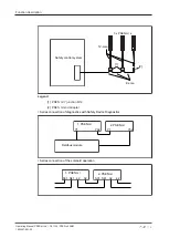
The auxiliary release enables guard locking to be opened from the access side to the
danger zone.
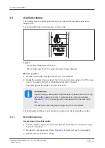
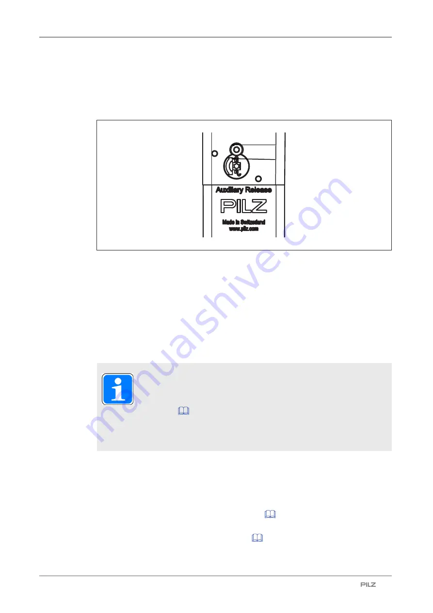
The safety switch has auxiliary releases on three sides.
[1]
[2]
Legend
[1] Auxiliary release screw Torx T10
[2] Security screw Torx T10, sealed with varnish when delivered
Mode of operation
1. Remove the security screw [2] using a Torx T10 screwdriver.
2. Rotate the auxiliary release screw [1] half a turn anti-clockwise using a Torx T10 screw-
driver. The guard locking pin is displaced and the bolt is released.
The safety gate to the danger zone can be opened.
INFORMATION
If guard locking is deactivated using the auxiliary release, there is a low sig-
nal at safety outputs 12 and 22. A warning will be output (see chapter
not
switch to the fault condi-
tion.
It is possible to open the guard locking using the control system.
The safety switch switches to normal operation when recommissioning without restart.
4.6.1
Recommissioning
Recommission the safety switch
1. Turn the auxiliary release screw [1] (see
) half a turn clockwise using a
Torx T10 screwdriver.
2. Re-insert the security screw [2] (see
Figure [
) using a Torx T10 screwdriver.
3. Seal the security screw with varnish.

