Adjustment
Operating Manual PSEN ml sa 1.1/2.1/2.2, PSEN ml DHM
1005457-EN-02
| 51
9
Adjustment
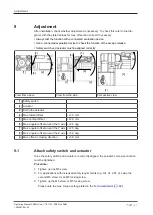
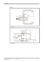
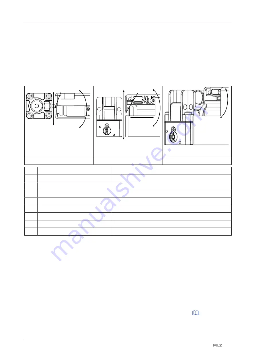
After installation, check whether adjustment is necessary. To check this refer to the dia-
grams with the stated values for max. offset and correct if necessary.
}
Always test the function with a connected evaluation device.
}
Use a connected evaluation device to check the function of the escape release.
}
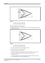
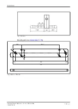
Safety switch and actuator must be aligned correctly
[1]
[2]
[4]
[3]
[8]
[1]
[2]
[3]
[5]
[7]
[9]
[1]
[2]
[6]
View from above
View from the side
Perspective view
[1] Safety switch
[2] Actuator
[3] Bolt in the actuator
[4] Max. lateral offset
+/-2.0 mm
[5] Max. vertical offset
+/-2.0 mm
[6] Max. angular offset around the X axis +/-2.0 deg
[7] Max. angular offset around the Y axis +/-2.5 deg
[8] Max. angular offset around the Z axis +/-5.0 deg
[9] Max. offset in closing direction
+/-5.0 mm
9.1
Attach safety switch and actuator
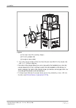
Once the safety switch and actuator are correctly aligned, the actuator's screw connection
must be tightened.
Procedure:
1. Tighten up one M5 screw.
2. For applications with increased safety requirements (e.g. SIL CL 2 PL d), swap the
second M5 screw for an M5 locking screw.
3. Tighten up the M5 screw or M5 locking screw.
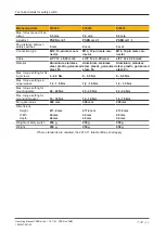
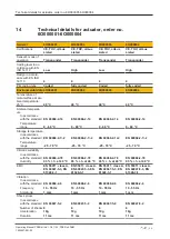
Please note the max. torque setting stated in the
.


