Function Description
Operating Manual PNOZ ml1p
21575-EN-06
13
The maximum reaction time for series connection of n base units
This is the time between the activation of a safety function at the input on one base unit and
the switching of an output on the connected base unit.
}
The maximum reaction time t
SUM
includes the following times:
t
ON
: Input delay = 4 ms
t
COND
: Switch-off delay of semiconductor output = 30 ms
t
REL
: Switch-off delay of relay output = 50 ms
t
BUS
: Data transmission time between two base units = 35 ms
n: Number of connections between base units
The maximum reaction time t
SUM
for series connection of n base units
}
On semiconductor outputs:
tS
UM
= t
ON
+ (n * t
BUS
) + t
COND
}
On relay outputs:
t
SUM
= t
ON
+ (n * t
BUS
) + t
REL
CAUTION!
For signals that are forwarded or received via the link module, a calculation
must always be made in accordance with the above formulas.
}
Input delay and switch-off delay are only included once in the reaction time. The data
transmission time between the link modules is multiplied by the number of connections.
}
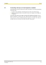
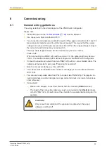
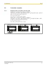
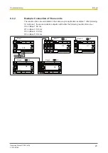
Please refer to the
Connection examples [
19]
.
CAUTION!
For signals that are forwarded or received via the link module, the overall
reaction time, e.g. the maximum reaction time of the series connection of n
base units, must always be considered in the risk assessment.
The risk assessment must consider all hazards as regards the reaction time
and the safety distance. The overall reaction time must not delay the arrival
of a safe condition by more than the permitted time.
Virtual inputs and outputs:
Inputs and outputs for both PNOZmulti systems are assigned in the PNOZmulti Configur-
ator. Inputs and outputs with the same number are assigned to each other, e.g. output o5
on one PNOZmulti system to input i5 on the other PNOZmulti system.


