- 3 -
Betriebsarten:
• Zweikanaliger Betrieb: Redundanter
Eingangskreis, Erdschlüsse im Tasterkreis
und Querschlüsse zwischen den Taster-
kontakten werden erkannt.
• Manueller Start: Gerät ist erst dann aktiv,
wenn ein Starttaster (im eigen- oder nicht
eigensicheren Bereich) betätigt wird.
• Manueller Start mit Überwachung: Gerät
ist erst aktiv, wenn der Starttaster betätigt
und wieder losgelassen wurde.
• Kontaktvervielfachung und -verstärkung
durch Anschluss von externen Schützen.
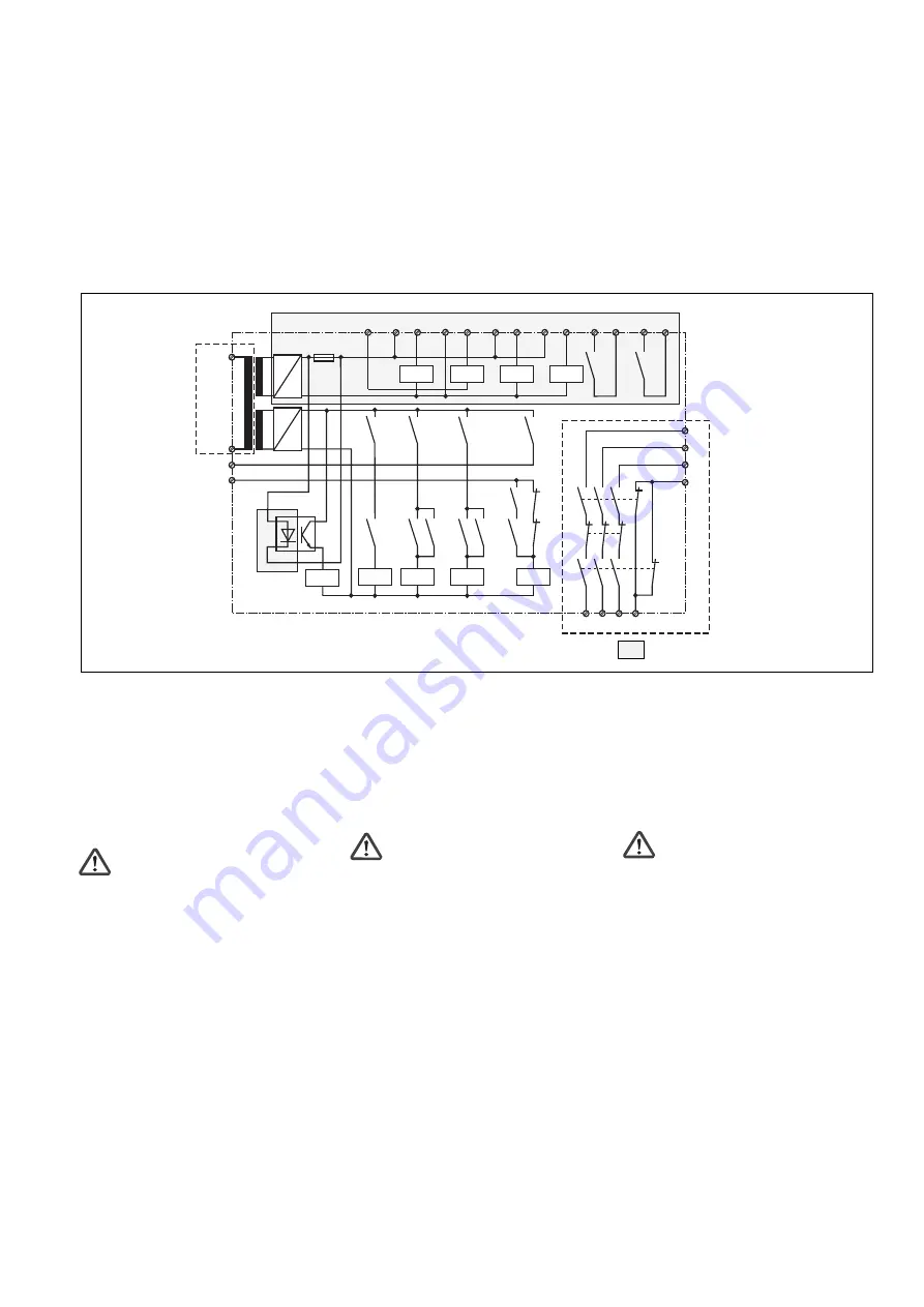
Fig. 1: Schematisches Schaltbild/Wiring diagram/Schéma interne
Eigensicherer Bereich/Intrinsically
safe area/Zone à sécurité intrinsèque
K2
K3
K1
K1
K2 K3
K3
K3
K1
K2
~
K4
S11
S52
S12 S21 S22 S33 S34 Y36 Y37
A2
A1
-
+
K8
53 54
K9
63 64
Y1
Y2
24
14
34 42
K1
K2
K3
K5
K6
K7
41
33
23
13
K7
K4
K5
K6
K8
K2
K1
F1
~
-
+
K9
U
B
*
*
* Isolation zum nicht markierten Bereich und der
Relaiskontakte zueinander: Basisisolierung
(Überspannungskategorie III), sichere Trennung
(Überspannungskategorie II)
* Insulation between the non-marked area
and the relay contacts: Basic insulation
(overvoltage category III), safe separation
(overvoltage category II)
* Isolation de la partie non sélectionnée par
rapport aux contacts relais : isolation basique
(catégorie de surtensions III), isolation
galvanique (catégorie de surtensions II)
Montage
Das Sicherheitsschaltgerät muss in einen
Schaltschrank mit einer Schutzart von mind.
IP54 eingebaut werden. Zur Befestigung auf
einer Normschiene hat das Gerät ein
Rastelement auf der Rückseite.
ACHTUNG!
• Gerät immer außerhalb des explosions-
gefährdeten Bereichs bzw. in einem Ex-
geschützten Einbauraum montieren. Nur
der eigensichere Ausgangsstromkreis
(Klemmen S11, S12, S21, S22, S33, S34,
S52, Y36, Y37 und GND) und die
potentialfreien Kontakte (Klemmen 53, 54
und 63, 64) dürfen in den explosions-
gefährdeten Bereich geführt werden.
• Luftstrecken zwischen blanken Teilen
eigensicherer Stromkreise und geerdeten
Metallteilen müssen mind. 3 mm betragen,
Luftstrecken zwischen blanken Teilen
eigensicherer Stromkreise und blanken
Teilen nicht eigensicherer Stromkreise
müssen mind. den in Tabelle 5 von
EN 60079-11:2007 geforderten Werten
entsprechen.
• Die Verdrahtung muss den Anforderungen
nach EN 60079-11:2011 Abs. 6.3.11
genügen.
Installation
The safety unit must be installed in a control
cabinet with a minimum protection type of
IP54. There is a notch on the rear of the unit
for DIN rail attachment.
CAUTION!
• The unit should always be installed outside
the potentially explosive area or inside an
Ex-protected space. Only the intrinsically
safe output circuit (terminals S11, S12,
S21, S22, S33, S34, S52, Y36, Y37 and
GND) and the volt-free contacts (terminals
53, 54 and 63, 64) may be brought into the
potentially explosive area.
• Air gaps between uninsulated parts of
intrinsically safe circuits and earthed metal
parts must be a minimum of 3 mm; air
gaps between uninsulated parts of
intrinsically safe circuits and uninsulated
parts of non-intrinsically safe circuits must
at least conform with the values required in
Table 5 of EN 60079-11:2007.
• The wiring must meet the requirements of
EN 60079-11:2011 clause 6.3.11.
Montage
Le bloc logique de sécurité doit être monté
dans une armoire ayant un indice de
protection d’au moins IP 54. Sa face arrière
permet un montage sur rail DIN.
ATTENTION !
• Montez impérativement l'appareil en
dehors de l'atmosphère explosible ou
dans un lieu d'implantation avec protection
Ex. Seul le circuit de sortie à sécurité
intrinsèque (bornes S11, S12, S21, S22,
S33, S34, S52, Y36, Y37 et GND) et les
contacts libres de potentiels (bornes 53,
54 et 63, 64) peuvent être câblés dans la
zone présentant des risques d’explosion.
• Les distances d’isolement entre les parties
dénudées des circuits électriques de
sécurité intrinsèque et les parties
métalliques raccordées à la terre doivent
être d’au moins 3 mm ; les distances
d’isolement entre les parties dénudées
des circuits électriques de sécurité
intrinsèque et les parties dénudées des
circuits électriques de sécurité non
intrinsèque doivent être conformes aux
valeurs mentionnées dans le tableau 5 de
l'EN 60079-11:2007.
• Le câblage doit satisfaire aux exigences
de l'EN 60079-11:2011,
paragraphe 6.3.11.
Operating modes:
• Dual-channel operation: Redundant input
circuit, earth faults in the pushbutton circuit
and shorts between the pushbutton
contacts are detected.
• Manual reset: The unit is not active until a
reset button (inside or outside the
intrinsically safe area) has been operated.
• Monitored manual reset: Unit is not active
until the reset button has been operated
and then released.
• Increase in the number of safety contacts
available by connecting external contactors.
Modes de fonctionnement :
• Commande par 2 canaux : circuit d’entrée
redondant, reconnaissance des mises à la
terre dans le circuit d’entrée et des courts-
circuits entre les contacts d’entrée.
• Réarmement manuel : l’appareil n’est activé
que lorsqu’un poussoir de réarmement (dans
la partie à sécurité intrinsèque ou celle non de
sécurité intrinsèque) est activé.
• Réarmement manuel auto-contrôlé : l’appareil
est uniquement actif lorsque le poussoir de
réarmement a été actionné, puis relâché.
• Augmentation du nombre de contacts ou du
pouvoir de coupure par l’utilisation de
contacteurs externes.


