


- 5 -
Les contacts de sécurité et le contact d’info
53-54 sont fermés, le contact d’info 41-42 est
ouvert. Les LED de visualisation "Channel 1",
"Channel 2" et "Ch1/Ch2" s’allument.
L’appareil est prêt à fonctionner.
Si le circuit d’entrée est ouvert, les contacts
de sécurité 13-14/23-24/33-34 et le contact
d’info 53-54 s’ouvrent, le contact d’info 41-42
se ferme. La LED de visualisation s’éteint.
Réactivation
• Fermez le circuit d’entrée
• Pour un réarmement manuel, actionnez le
poussoir de réarmement.
• Dans le cas d’un réarmement manuel
surveillé, appuyez sur le poussoir de
réarmement, puis relâchez-le.
La LED de visualisation s’allume à nouveau,
le circuit d’entrée est réactivé.
Ne raccordez l’appareil que conformé-
ment aux illustrations ci-après !
Die Sicherheitskontakte und der Hilfskontakt
53-54 sind geschlossen, der Hilfkontakt 41-
42 ist geöffnet. Die Statusanzeigen "Channel
1", "Channel 2" und "Ch1/Ch2" leuchten. Das
Gerät ist betriebsbereit.
Wird der Eingangskreis geöffnet, öffnen die
Sicherheitskontakte 13-14/23-24/33-34 und
der Hilfskontakte 53-54, der Hilfskontakt 41-
42 schließt. Die Statusanzeige erlischt.
Wieder aktivieren
• Eingangskreis schließen
• Bei manuellem Start zusätzlich Startaster
betätigen.
• Bei manuellem überwachten Start den
Starttaster betätigen und wieder loslassen.
Die Statusanzeigen leuchten wieder, der
Eingangskreis ist aktiviert.
Das Gerät nur wie in den folgenden
Abbildungen anschließen!
If the input circuit is opened, safety contacts
13-14/23-24/33-34 and auxiliary contact
53-54 will open, auxiliary contact 41-42
closes. The status indicator will go out.
Reactivate
• Close the input circuit
• With manual reset, also press the reset
button.
• With monitored manual reset, press the
reset button and then release it.
The status indicators light up again, the input
circuit is activated.
Only connect the unit as shown in the
following diagrams!
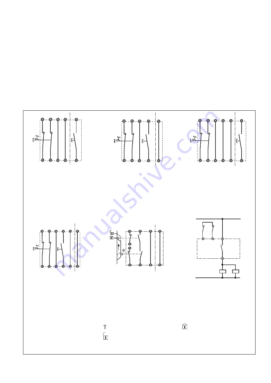
Fig. 2:
Eingangskreis zweikanalig: Not-Halt-Be-
schaltung; manueller Start im nicht
eigensicheren Bereich/Dual-channel input
circuit: E-STOP wiring; manual reset in the
non-intrinsically safe area/Circuit d’entrée à
deux canaux : connexion AU ; réarmement
manuel dans la zone non de sécurité
intrinsèque
Fig. 3:
Eingangskreis zweikanalig; Not-Halt-Be-
schaltung; manueller Start im eigensicheren
Bereich/Dual-channel input circuit; E-STOP
wiring; manual reset in the intrinsically safe
area/Circuit d’entrée à deux canaux ;
connexion AU ; réarmement manuel dans la
zone à sécurité intrinsèque
Fig. 4:
Eingangskreis zweikanalig; Not-Halt-
Beschaltung; manueller, überwachter Start
im nicht eigensicheren Bereich/Dual-
channel input circuit; E-STOP wiring;
monitored manual reset in the non-
intrinsically safe area/Circuit d’entrée à
deux canaux ; connexion AU ; réarmement
manuel surveillé dans la zone non de
sécurité intrinsèque
S11 S21
Y1
S12
S12
S34
Y2
S22
Y36
S52
S1
S3
S11 S21
Y1
S12
S12
S34
Y2
S22
Y36
S52
S3
S1
S11 S21
Y1
S12
S12
S34
Y2
S22
Y36
S52
S33
Y37
S1
S3
Fig. 6:
Zweikanalige Schutztürsteuerung; Stellungs-
überwachung im eigensicheren Bereich/
Dual-channel safety gate control; position
monitoring in the intrinsically safe area/
Commande de porte de protection à deux
canaux ; surveillance de position en zone à
sécurité intrinsèque
Fig. 7:
Anschlussbsp. für externe Schütze/
Connection eg. for external contactors/
Exemple de raccordement pour des
contacteurs externes
Fig. 5:
Eingangskreis zweikanalig; Not-Halt-
Beschaltung; manueller, überwachter Start
im eigensicheren Bereich/Dual-channel
input circuit; E-STOP wiring; monitored
manual reset in the intrinsically safe area/
Circuit d’entrée à deux canaux ; connexion
AU ; réarmement manuel surveillé dans la
zone à sécurité intrinsèque
S11 S21
S33
S12
S12
S34 Y37
S22
Y36
S52
Y1
Y2
S1
S3
S22
S34
S33
S21
S11
S52
S12
S1
S2
S11
Y2
Y1
14
K4
K5
13
Y1
Y2
K4
K5
1L1
1L2
Tür geschlossen/Gate closed/Porte
fermée
S1/S2: Not-Halt-bzw. Schutztürschalter/E-
STOP or safety gate switch/
Commutateur AU ou interrupteur
de porte de protection
S3:
Starttaster/Reset button/Poussoir
de réarmement
Tür nicht geschlossen/Gate open/Porte
ouverte
betätigtes Element/Switch operated/
Elément actionné


