background image

- 7 -

Circuits non de sécurité intrinsèque
• Circuit d’alimentation non de sécurité

intrinsèque, raccordement par les bornes
A1 et A2

Nichteigensichere Stromkreise
• Nichteigensicherer Versorgungsstromkreis,

Anschluss über Klemmen A1 und A2

Non-intrinsically safe circuits
• Non-intrinsically safe supply circuit,

connection via terminals A1 and A2

Artikel-Nr./Item no./Ref. article

774 101

774 104

774 105

774 100

774 099

Typ/Type

PNOZ Ex 42VAC

PNOZ Ex 115VAC

PNOZ Ex 120VAC

PNOZ Ex 230VAC

PNOZ Ex -R 230VAC

Versorgungsspannung/Supply voltage/

Tension d’alimentation

42 VAC +10 % -15 %

115 VAC  +10 % -15 %

120 VAC  +10 % -15 %

230 VAC  +10 % -15 %

230 VAC  +10 % -15 %

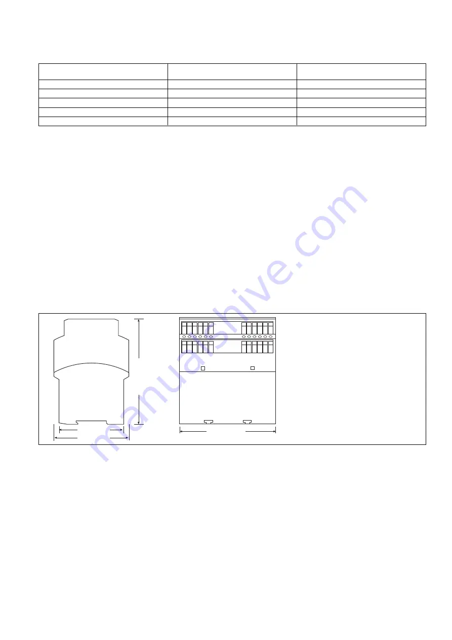
Abmessungen in mm (")/Dimensions in mm (")/Dimensions en mm (")

112,5 (4.41")

121 (4.76")

75  (2.95")

87 (3.42")

- Umgebungstemperaturbereich: -20 bis

+55 °C

- Schutzart: Gehäuse IP40, Klemmen-

bereich IP20

• Nichteigensicherer Ausgangsstromkreis

(Rückführkreis), Anschluss über Klemmen
Y1 und Y2
- Nennausgangsspannung: 24 V DC
- Nennausgangsstromstärke: 20 mA
- nur zum Anschluss einer Drahtbrücke

oder eines Schaltkontaktes

• Nichteigensichere Kontaktstromkreise,

Anschluss über Klemmen 13 und 14, 23
und 24, 33 und 34, sowie 41 und 42
- Schaltvermögen:

AC 240 V / 4 A / 1000 VA,
DC 24 V / 2 A / 48 W

- Absicherung der Kontaktstrecken: 4 A T

- Ambient temperature range: -20 to

+55 °C

- protection type: housing IP40, terminals

IP20

• Non-intrinsically safe output circuit

(feedback loop), connection via terminals
Y1 and Y2
- rated output voltage: 24 V DC
- rated output current strength: 100 mA
- only for connecting a jumper or switch

contact

• Non-intrinsically safe contact circuits,

connection via terminals 13 and 14, 23
and 24, 33 and 34, plus 41 and 42
- switching capability:

AC 250 V / 4 A / 1000 VA,
DC 24 V / 2 A / 48 W

- protection of contact paths: 4 A T

- Plage de température ambiante : -20 à

+55 °C

- Indice de protection : boîtier IP40,

bornier IP20

• Circuit de sortie non de sécurité intrinsèque
(boucle de retour), raccordement par les

bornes Y1 et Y2
- Tension de sortie nominale : 24 V DC
- Courant de sortie nominal : 100 mA
- Prévu uniquement pour le raccordement

d’un pont ou d’un contact de
commutation

• Circuits de contact non de sécurité

intrinsèque, raccordement par les bornes 13
et 14, 23 et 24, 33 et 34, ainsi que 41 et 42
- Caractéristiques de commutation :

AC 250 V / 4 A / 1000 VA,
DC 24 V / 2 A / 48 W

- Protection par fusible des contacts : 4 A T

Summary of Contents for 774 099

Page 1: ...p rieures la basse tension 50 V AC ou 120 V DC les l ments de commande et les capteurs raccord s doivent supporter une tension d isolement assign e d au moins 250 V Utilisation conforme Le bloc logiqu...

Page 2: ...u dispositif de s curit sont test es automatiquement chaque cycle marche arr t de la machine Un fusible assure la protection contre les court circuits Descriptif du fonctionnement Le bloc logique de s...

Page 3: ...intrinsically safe output circuit terminals S11 S12 S21 S22 S33 S34 S52 Y36 Y37 and GND and the volt free contacts terminals 53 54 and 63 64 may be brought into the potentially explosive area Air gap...

Page 4: ...de c blage en cuivre r sistant des temp ratures de 60 75 C Lors du raccordement de d tecteurs de proximit magn tiques bas s sur des contacts Reed veuillez vous assurer que le courant de cr te max la...

Page 5: ...t im nicht eigensicheren Bereich Dual channel input circuit E STOP wiring manual reset in the non intrinsically safe area Circuit d entr e deux canaux connexion AU r armement manuel dans la zone non d...

Page 6: ...iable partir du num ro de s rie s quentiel 6 chiffres Pour chaque num ro de s rie une liste contenant les donn es de fabrication est enregistr e Plage de temp rature 20 C Ta 55 C Symbole CE CE 0123 n...

Page 7: ...stromkreise Anschluss ber Klemmen 13 und 14 23 und 24 33 und 34 sowie 41 und 42 Schaltverm gen AC 240 V 4 A 1000 VA DC 24 V 2 A 48 W Absicherung der Kontaktstrecken 4 A T Ambient temperature range 20...

Page 8: ...in input resistance when switching on Max line capacitance EX I IIB IIIC EX IIC Max line inductance EX I IIB IIIC EX IIC Safety related characteristics of the safety outputs PL in accordance with EN I...

Page 9: ...anical data Housing material Housing Front Cable cross section screw terminals 1 core flexible 2 core same cross section flexible with crimp connectors without insulating sleeve without crimp connecto...

Page 10: ...e service life graphs are met The PFH value depends on the switching frequency and the load on the relay output If the service life graphs are not accessible the stated PFH value can be used irrespect...

Page 11: ...de sortie Lebensdauerkurve Die Lebensdauerkurven geben an ab welcher Schaltspielzahl mit verschlei bedingten Ausf llen gerechnet werden muss Der Verschlei wird vor allem durch die elektrische Belastun...

Page 12: ...w terminals borniers vis Schraubklemmen screw terminals borniers vis Schraubklemmen screw terminals borniers vis Bestell Nr Order no R f rence 774 101 774 100 774 104 774 105 774 099 Bestelldaten Orde...

Reviews: