- 2 -
• Sicherheitseinrichtung bleibt auch bei Aus-
fall eines Bauteils wirksam.
• Bei jedem Ein-Aus-Zyklus der Maschine
wird automatisch überprüft, ob die Relais
der Sicherheitseinrichtung richtig öffnen
und schließen.
Description du fonctionnement
Le relais PNOZ X2/X2.1/X2.2 assure de
façon sure, l’ouverture d’un circuit de
sécurité. A la mise sous tension du relais
(A1-A2), la LED "POWER" s'allume. Le
relais est activé si le circuit de réarmement
S33-S34 est fermé.
• Circuits d'entrée fermés (poussoir AU non
actionné) :
Les relais K1 et K2 passent en position
travail et s'auto-maintiennent. Les LEDs
"CH.1" et CH.2" s'allument. Les contacts
de sécurité (13-14/23-24) sont fermés.
• Circuits d'entrée ouverts (poussoir AU
actionné) :
Les relais K1 et K2 retombent. Les LEDs
"CH.1" et "CH.2" s'éteingnent. Les
contacts de sécurité (13-14/23) s'ouvrent.
Function Description
The relay PNOZ X2/X2.1/X2.2 provides a
safety-oriented interruption of a safety circuit.
When the operating voltage is supplied the
LED "POWER" is illuminated. The unit is
ready for operation, when the reset circuit
S33-S34 is closed.
• Input Circuit closed (e.g. the Emergency
Stop button is not pressed):
Relays K1and K2 energise and retain
themselves. The status indicators for
"CH.1" and "CH.2" illuminate. The safety
contacts (13-14/23-24) are closed.
• Input Circuit is opened (e.g. Emergency
Stop is pressed)
Relays K1 and K2 de-energise. The
status indicators for "CH.1" and "CH.2" go
out. The safety contacts (13-14/23-24) will
be opened (redundant).
• The safety function remains effective in
the case of a component failure.
• The correct opening and closing of the
safety function relays is tested
automatically in each on-off cycle.
• sécurité garantie même en cas de
défaillance d’un composant
• test cyclique (ouverture/fermeture des
relais internes) à chaque cycle Marche/
Arrêt de la machine
Funktionsbeschreibung
Das Schaltgerät PNOZ X2/X2.1/X2.2 dient
dem sicherheitsgerichteten Unterbrechen
eines Sicherheitsstromkreises. Nach
Anlegen der Versorgungsspannung leuchtet
die LED "POWER". Das Gerät ist betriebsbe-
reit, wenn der Startkreis S33-S34 geschlos-
sen ist.
• Eingangskreis geschlossen (z. B. Not-
Halt-Taster nicht betätigt):
Relais K1 und K2 gehen in Wirkstellung
und halten sich selbst. Die Statusanzeigen
"CH.1" und "CH.2" leuchten. Die Sicher-
heitskontakte 13-14/23-24 sind geschlos-
sen.
• Eingangskreis wird geöffnet (z. B. Not-
Halt-Taster betätigt):
Relais K1 und K2 fallen in die Ruhe-
stellung zurück. Die Statusanzeige für
"CH.1" und "CH.2" erlischt. Die Sicher-
heitskontakte 13-14/23-24 werden
redundant geöffnet.
Betriebsarten:
• Einkanaliger Betrieb:
Eingangsbeschaltung nach VDE 0113
Teil 1 und EN 60204-1; keine Redundanz
im Eingangskreis; Erdschlüsse im
Startkreis werden erkannt. Bei Erdschlüs-
sen im Not-Halt-Kreis löst die Sicherung
der Versorgungsspannung aus.
• Zweikanaliger Betrieb: Redundanter Ein-
gangskreis, Erdschlüsse im Tasterkreis
und Querschlüsse zwischen den Taster-
kontakten werden erkannt.
• Nur PNOZ X2.1: automatischer Start:
Gerät ist aktiv, sobald Eingangskreis
geschlossen ist.
• Manueller Start: Gerät ist erst dann aktiv,
wenn ein Starttaster betätigt oder ein
Startkontakt geschlossen wird.
• Nur PNOZ X2/X2.2: manueller Start mit
Überwachung: vor dem Schließen des
Startkontakts muss die Versorgungs-
spannung anliegen. Das Gerät ist erst
aktiv, wenn danach der Starttaster betätigt
wurde. Dadurch ist eine automatische
Aktivierung durch Überbrückung des
Starttasters ausgeschlosssen.
Operating Modes
• Single-channel operation: Input wiring
according to VDE 0113 part 1 and
EN 60204-1, no redundancy in the input
circuit. Earth faults are detected in the
reset circuit. Earth faults in the Emergency
Stop circuit trigger the internal electronic
fuse.
• Two-channel operation: Redundancy in the
input circuit. Earth faults in the Emergency
Stop circuit and shorts across the
emergency stop push button are also
detected.
• Only PNOZ X2.1: Automatic reset: Unit is
active as soon as the input circuit is
closed.
• Manual reset: Unit is only active when a
reset button has been pressed or reset
contact is closed.
• Only PNOZ X2/X2.2: monitored manual
reset: The operating voltage must be
applied before the closing of start/reset
contacts. The unit is only active if after,
the reset button is pressed. This prevents
automatic reset and will detect stuck or
short-circuited reset button.
Modes de fonctionnement
• Commande par 1 canal : conforme aux
prescriptions de la EN 60 204-1 pas de
redondance dans le circuit d’entrée. La
mise à la terre du circuit de réarmement
est détectée. En cas de mise à la terre
des circuits d'entrée, le fusible
électronique déclenche.
• Commande par 2 canaux: circuit d’entrée
redondant. La mise à la terre et les courts-
circuits entre les contacts sont détectées.
• PNOZ X2.1 uniquement: réarmement
automatique : le relais est activé dès la
fermeture des canaux d’entrée.
• Réarmement manuel : le relais n’est activé
qu’après une impulsion sur un poussoir de
validation.
• PNOZ X2/X2.2 uniquement:
réarmement manuel auto-contrôlé: La
tension d'alimentation doit être avant la
fermeture du circuit de réarmement. Le
relais n'est alors activé qu'après une
impulsion sur le poussoir de réarmement.
De ce fait un réarmement automatique ou
un pontage du poussoir de validation est
impossible.
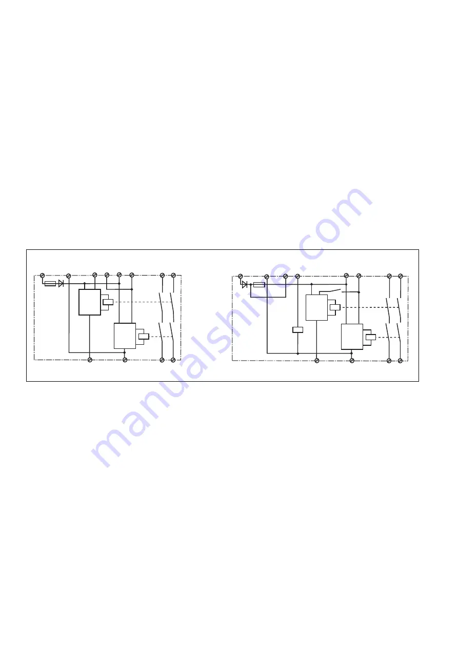
Fig. 1: Innenschaltbild/Internal Wiring Diagram/Schéma de principe
A1 (L+)
A2 (L-)
S22
S12
S21
S11
S33
13
14
K1
K2
23
24
S34
Start
Unit
Start
Unit
A1 (L+)
A2 (L-)
S22
S12
S21
S11
S34
13
14
K1
K2
23
24
S33
Start
Unit
Start
Unit
K3
K3
PNOZ X2, PNOZ X2.1
PNOZ X2.2