background image

PNOZ e1.1p

Operating Manual PNOZ e1.1p
21238-EN-06

29

Times

774133

784133

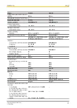
Supply interruption before de-ener-
gisation

20 ms

20 ms

Simultaneity, channel 1 and 2 max.

Environmental data

774133

784133

Climatic suitability

EN 60068-2-78

EN 60068-2-78

Ambient temperature

Temperature range

-10 - 55 °C

-10 - 55 °C

Storage temperature

Temperature range

-25 - 70 °C

-25 - 70 °C

Climatic suitability

Humidity

93 % r. h. at 40 °C

93 % r. h. at 40 °C

Condensation during operation

Not permitted

Not permitted

EMC

EN 60947-5-1, EN 61000-6-2, EN
61000-6-4, EN 61326-3-1

EN 60947-5-1, EN 61000-6-2, EN
61000-6-4, EN 61326-3-1

Vibration

In accordance with the standard

EN 60068-2-6

EN 60068-2-6

Frequency

10 - 55 Hz

10 - 55 Hz

Amplitude

0,35 mm

0,35 mm

Airgap creepage

In accordance with the standard

EN 60947-1

EN 60947-1

Overvoltage category

III

III

Pollution degree

2

2

Rated insulation voltage

30 V

30 V

Rated impulse withstand voltage

0,8 kV

0,8 kV

Protection type

Mounting area (e.g. control cab-
inet)

IP54

IP54

Housing

IP40

IP40

Terminals

IP20

IP20

Mechanical data

774133

784133

Mounting position

Any

Any

Material

Bottom

PPO UL 94 V0

PPO UL 94 V0

Front

ABS UL 94 V0

ABS UL 94 V0

Top

PPO UL 94 V0

PPO UL 94 V0

Connection type

Screw terminal

Spring-loaded terminal

Mounting type

plug-in

plug-in

Conductor cross section with screw
terminals

1 core flexible

0,25 - 2,5 mm², 24 - 12 AWG

2 core with the same cross sec-
tion, flexible with crimp connect-
ors, no plastic sleeve

0,25 - 1 mm², 24 - 16 AWG

2 core with the same cross sec-
tion, flexible without crimp con-
nectors or with TWIN crimp con-
nectors

0,2 - 1,5 mm², 24 - 16 AWG

Summary of Contents for 774133

Page 1: ...PNOZ e1 1p Operating Manual 21238 EN 06 Safety relays ...

Page 2: ...cumentation will be gratefully received Source code from third party manufacturers or open source software has been used for some components The relevant licence information is available on the Internet on the Pilz homepage Pilz PIT PMI PNOZ Primo PSEN PSS PVIS SafetyBUS p SafetyEYE SafetyNET p the spirit of safety are registered and protected trademarks of Pilz GmbH Co KG in some countries SD mea...

Page 3: ...al 7 Unit features 8 Safety features 8 Block diagram terminal configuration 8 Function description 9 Operating modes 9 Selecting sensors 10 Installation 10 Wiring 11 Preparing for operation 12 Supply voltage 12 Input circuit 12 Start circuit 13 Feedback loop 13 Logic connection between several units 15 Logic input S35 and S36 16 Examples 17 Operation 21 Status indicators 21 Faults Interference 22 ...

Page 4: ...Contents Operating Manual PNOZ e1 1p 21238 EN 06 4 Remove plug in terminals 31 Order reference 31 Product 31 Accessories 31 ...

Page 5: ...ularly important is identified as follows DANGER This warning must be heeded It warns of a hazardous situation that poses an immediate threat of serious injury and death and indicates preventive measures that can be taken WARNING This warning must be heeded It warns of a hazardous situation that could lead to serious injury and death and indicates preventive measures that can be taken CAUTION This...

Page 6: ...see Technical details 27 NOTICE EMC compliant electrical installation The product is designed for use in an industrial environment The product may cause interference if installed in other environments If installed in other environments measures should be taken to comply with the applicable standards and directives for the respective installation site with regard to in terference Safety regulations...

Page 7: ...t preven tion Have read and understood the information provided in this description under Safety And have a good knowledge of the generic and specialist standards applicable to the specific application Warranty and liability All claims to warranty and liability will be rendered invalid if The product was used contrary to the purpose for which it is intended Damage can be attributed to not having f...

Page 8: ...ty contacts 2 logic inputs AND OR for logic connections between several units Feedback loops for monitoring external contactors Detection of shorts across contacts via test pulse outputs Safety features The relay meets the following safety requirements The circuit is redundant with built in self monitoring The safety device remains effective in the case of a component failure The safety outputs ar...

Page 9: ...loop input must close within 150 ms If a contact is still open after 150 ms has elapsed an error is detected and is displayed as a flashing code 1 8 see Faults Interference 22 It will not be pos sible to switch the unit back on until the error has been rectified and the supply voltage has been switched off and then on again AND OR connection The PNOZ e1 1p has two logic inputs S35 OR and S36 AND f...

Page 10: ...ts are only permitted if the PNOZelog is oper ated without detection of shorts across contacts Installation CAUTION Electrostatic discharge can damage components on the safety system Ensure against discharge before touching the safety system e g by touch ing an earthed conductive surface or by wearing an earthed armband The unit should be installed in a control cabinet with a protection type of at...

Page 11: ...e the terminal block with filter see Order reference 31 You must comply with the idling capacity at safety outputs 14 and 24 see Technical details 27 Do not connect undesignated terminals Output Y32 is an auxiliary output e g for communication with a PLC or text display Auxiliary output Y32 should not be used for safety circuits Only contactors with positive guided contacts should be used for safe...

Page 12: ... in the table in the section entitled Logic connection between several units 16 Input circuit Single channel Dual channel E STOP without detection of shorts across contacts E STOP with detection of shorts across contacts Safety gate without detection of shorts across contacts Y4 S11 A1 S12 S22 Y4 S11 S12 S22 A1 Safety gate with detection of shorts across contacts S11 S12 S21 S22 Y4 S21 S21 Light g...

Page 13: ... start up test E STOP wiring Safety gate with start up test NOTICE With automatic start The unit starts up automatically when the safeguard is reset e g when the E STOP pushbutton is released Use external circuit measures to prevent an unexpected restart Feedback loop Contacts from external contactors can be connected between Y6 and A1 Feedback loop unconnected If you do not wish to connect any co...

Page 14: ...PNOZ e1 1p Operating Manual PNOZ e1 1p 21238 EN 06 14 Example The positive guided contacts of contactors K1 and K2 control the feedback loop ...

Page 15: ...owest SIL PL value determines the SIL PL value of the entire circuit PNOZ e1p PNOZ e8 1p These units do not have logic inputs Their safety outputs can be used to logically link the units to the logic inputs of other PNOZelog units or to the cascading inputs from PNOZmulti units Safety outputs from the PNOZ e1p are suitable for logic connections from unit version 3 0 Each safety output on a PNOZelo...

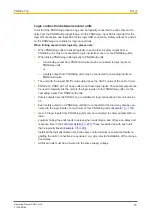
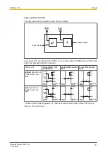
Page 16: ...ction Logic AND connec tion Logic OR connec tion without detection of shorts across con tacts Y4 S36 S35 14 24 14 24 PNOZ e1 1p Unit 1 Unit 2 AND OR A1 1 Y4 S36 14 24 PNOZ e1 1p Unit 1 AND A1 1 Y4 S35 14 24 PNOZ e1 1p Unit 1 OR S11 with detection of shorts across con tacts Y4 S36 S35 14 24 14 24 PNOZ e1 1p Unit 1 Unit 2 AND OR 1 Y4 S36 14 24 PNOZ e1 1p Unit 1 AND 1 Y4 S35 14 24 PNOZ e1 1p Unit 1 O...

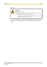
Page 17: ...s safety function and can lead to the most serious injuries and death Before using the OR function carry out a risk analysis and use other measures to establish a safe condition The following examples represent various ways in which PNOZelog units can be logically connected In all the application examples 2 loads may also be connected to the safety outputs ...

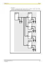
Page 18: ... e1 1p Operating Manual PNOZ e1 1p 21238 EN 06 18 Example 1 Loads are connected to the safety outputs of Unit 1 In addition a safety output is AND linked to 4 other PNOZelog units via the logic input S36 14 ...

Page 19: ...OZ e1 1p Operating Manual PNOZ e1 1p 21238 EN 06 19 Example 2 Loads are connected to the safety outputs of Unit 1 In addition a safety output is AND linked to another PNOZelog unit via the logic input S36 ...

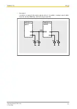
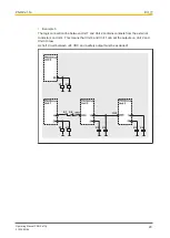
Page 20: ...onnection line between Unit 1 and Unit 2 contains contacts from the external contactors on Unit 4 This means that Unit 4 and Unit 1 can set the outputs on Unit 2 and Unit 3 to low A short circuit between 24 VDC and a safety output must be excluded K5 K6 K3 K4 K7 K8 K7 K1 K2 K8 ...

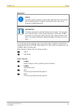
Page 21: ... test pulses also mean that when measured with a multi meter the voltage at the safety outputs is displayed to be less than it actu ally is The unit detects the set operating mode once supply voltage is applied During this time initialisation phase the POWER LED will flash The unit is ready for operation when the POWER LED is lit continuously LEDs indicate the status and errors during operation LE...

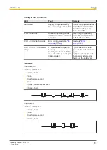
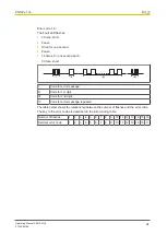
Page 22: ...g the LEDs There are faults that are displayed via periodic flashing see table Display of fault conditions and faults where an error code can be determined via the number of flashes see table Relationship between the number of flashes and the decimal error code 24 These faults are always indicated by three short flashes at LED CH 1 or CH 2 After a longer pause the LED will then flash at one second...

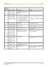
Page 23: ...test CH 1 or CH 2 flash a code Error coding see table Er ror code 25 See table Error code 25 CH 1 and CH 2 flash altern ately 1 Feedback loop open on start up 2 Only one channel of the input circuit is open or is par tially operated 1 Close feedback loop open input circuit start unit again 2 Open both input circuit channels or activate and then clear the safety mat Examples Error code 1 3 The Faul...

Page 24: ...hort I Code for error message II Code for 1st digit III Code for 2nd digit IV Code for error message repeated The table below shows the relationship between the number of flashes and the error code The key to the error codes is described in the Error coding table Number of flashes 1 2 3 4 5 6 7 8 9 10 11 12 13 14 15 16 Decimal error code 1 2 3 4 5 6 7 8 9 10 11 12 13 14 15 0 ...

Page 25: ...s 14 24 10 1 0 1 1 1 9 10 1 14 5 3x short 10x long 3x short 3x short 1x long 16x long 3x short 3x short 1x long 1x long 3x short 3x short 1x long 9x long 3x short 3x short 10x long 1x long 3x short 3x short 14x long 5x long 3x short During operation short circuit between the safety outputs and 24 VDC Rectify wiring error at terminals 14 24 1 2 1 3 1 12 1 13 3x short 1x long 2x long 3x short 3x sho...

Page 26: ...ort 5x long 10x long 3x short UB 19 2 VDC Keep within the supply voltage range of 19 2 30 VDC 8 1 3x short 8x long 1x long 3x short Invalid operating mode Check wiring for the operating mode and rectify fault 8 2 8 3 14 13 3x short 8x long 2x long 3x short 3x short 8x long 3x long 3x short 3x short 14x long 13x long 3x short Supply interrupted possibly caused by a short to earth Rectify wiring err...

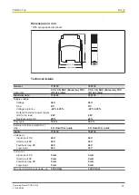
Page 27: ...tage tolerance 20 25 20 25 Output of external power supply DC at no load 2 W 2 W Residual ripple DC 20 20 Duty cycle 100 100 External unit fuse protection F1 max 6 A slow 10 A quick 6 A slow 10 A quick Inputs 774133 784133 Voltage at Input circuit DC 24 V 24 V Start circuit DC 24 V 24 V Feedback loop DC 24 V 24 V Logic input 24 V 24 V Current at Input circuit DC 5 mA 5 mA Start circuit DC 5 mA 5 m...

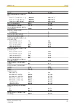
Page 28: ...1 5 A Power at UB 26 5 V 50 W 50 W Power at UB 26 5 V 45 W 45 W Switching capability 1 safety out put under load Current at UB 26 5 V 2 7 A 2 7 A Current at UB 26 5 V 2 2 A 2 2 A Power at UB 26 5 V 70 W 70 W Power at UB 26 5 V 65 W 65 W Max line capacitance at the out puts without load 2 nF 2 nF Voltage auxiliary and test pulse outputs 24 V 24 V Current auxiliary and test pulse outputs 0 5 A 0 5 A...

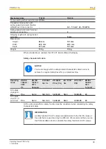
Page 29: ...plitude 0 35 mm 0 35 mm Airgap creepage In accordance with the standard EN 60947 1 EN 60947 1 Overvoltage category III III Pollution degree 2 2 Rated insulation voltage 30 V 30 V Rated impulse withstand voltage 0 8 kV 0 8 kV Protection type Mounting area e g control cab inet IP54 IP54 Housing IP40 IP40 Terminals IP20 IP20 Mechanical data 774133 784133 Mounting position Any Any Material Bottom PPO ...

Page 30: ...the safety related characteristic data in order to achieve the required safety level for your plant machine Operating mode EN ISO 13849 1 2015 PL EN ISO 13849 1 2015 Category EN 62061 SIL CL EN 62061 PFHD 1 h IEC 61511 SIL IEC 61511 PFD EN ISO 13849 1 2015 TM year SC output via logic in put PL e Cat 4 SIL CL 3 3 61E 09 SIL 3 5 82E 05 20 SC output via 2 ch in put circuit PL e Cat 4 SIL CL 3 3 44E 0...

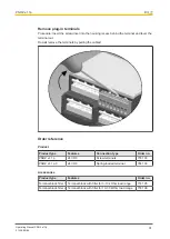
Page 31: ...rminals by pulling the cables Order reference Product Product type Features Connection type Order no PNOZ e1 1p 24 VDC Screw terminals 774 133 PNOZ e1 1p C 24 VDC Spring loaded terminal 784 133 Accessories Product type Features Order no Terminal block filter 1 Terminal block with filter for 3 10 kOhm load range 774 195 Terminal block filter 2 Terminal block with filter for 10 30 kOhm load range 77...

Page 32: ...ET p the spirit of safety are registered and protected trademarks of Pilz GmbH Co KG in some countries We would point out that product features may vary from the details stated in this document depending on the status at the time of publication and the scope of the equipment We accept no responsibility for the validity accuracy and entirety of the text and graphics presented in this information Pl...

Reviews: