

PZE X5
Operating Manual PZE X5
1003301EN05
13
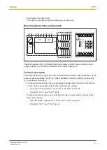
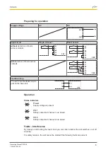
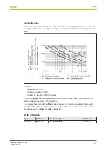
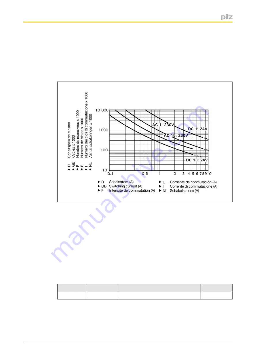
Service life graph
The service life graphs indicate the number of cycles from which failures due to wear must
be expected. The wear is mainly caused by the electrical load; the mechanical load is negli
gible.
Example
}
Inductive load: 0,2 A
}
Utilisation category: AC15
}
Contact service life: 4,000,000 cycles
Provided the application requires fewer than 4,000,000 cycles, the PFH value (see tech
nical details) can be used in the calculation.
To increase the service life, sufficient spark suppression must be provided on all output
contacts. With capacitive loads, any power surges that occur must be noted. With contact
ors, use freewheel diodes for spark suppression.
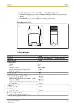
Order reference
Type
Features
Connection type
Order no.
PZE X5
24 V DC
Screw terminals
774595


