

PZE X5
Operating Manual PZE X5
1003301EN05
8
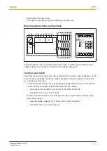
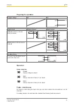
Preparing for operation
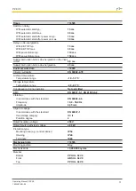
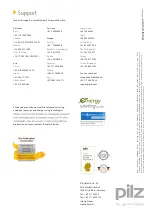
Supply voltage
AC
DC
A1
L+
A2
L-
Input circuit
Singlechannel
Dualchannel
without
detection of shorts
across contacts
K1
K2
U
Y4
Y3
PZE
K1
K2
U
Y4
Y3
PZE
U
with
detection of shorts across
contacts
K1
K2
U
Y4
Y3
PZE
U
Feedback loop
Y1 and Y2 are feedback loop in
puts on the base unit
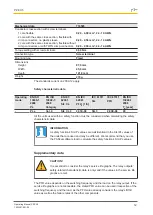
Operation
Status indicators
Power
Supply voltage is present.
CH.1
Safety contacts of channel 1 are closed.
CH.2
Safety contacts of channel 2 are closed.
Faults – Interference
By closing or interrupting the input circuit you can check whether the unit switches on or off
correctly.
For safety reasons, the unit cannot be started if the following faults are present:


