background image

Operating Manual PMCenergy SD
1004547-EN-01

Description of the device 

En

gl

is

h

12

2.6

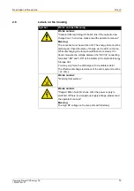
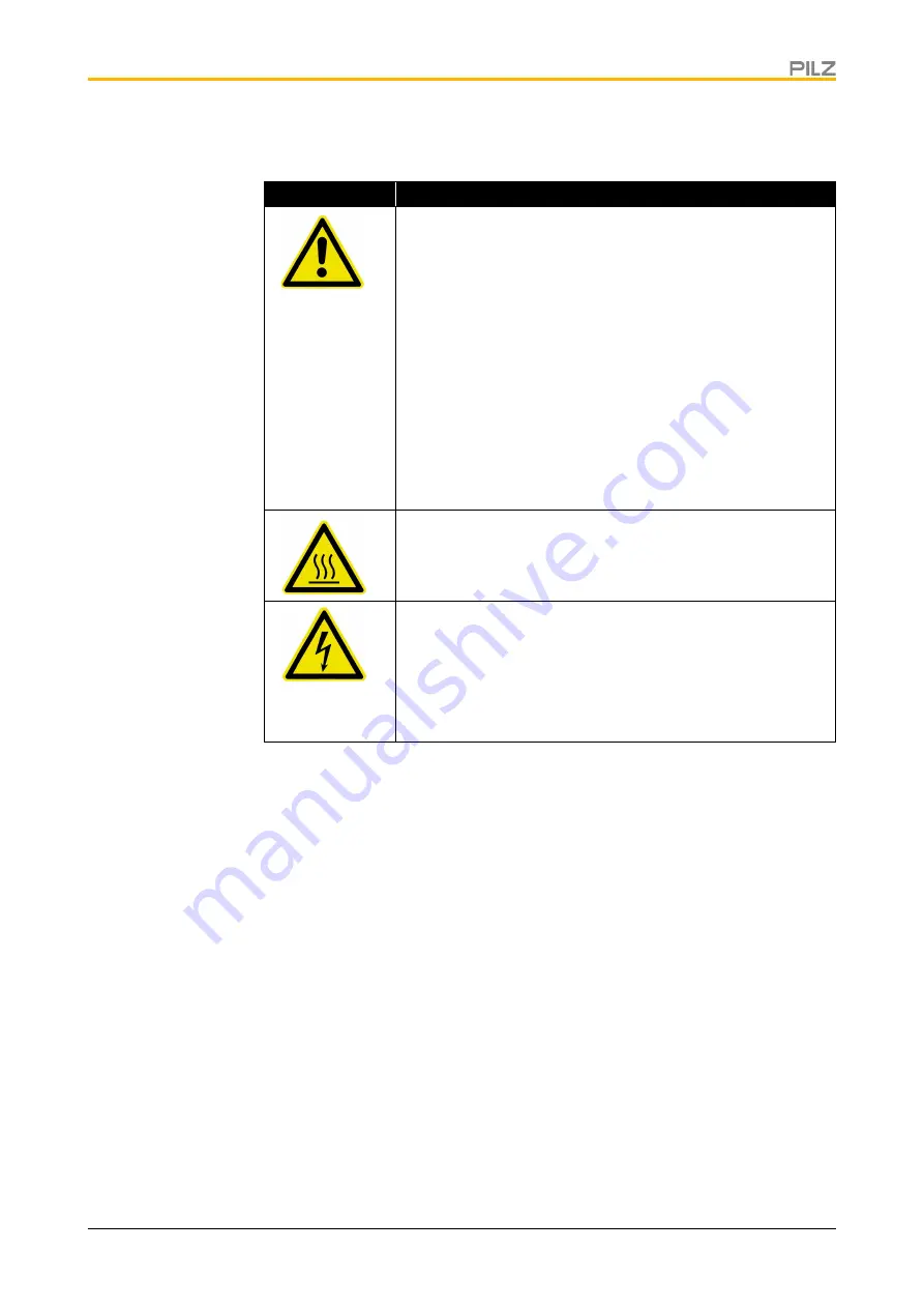
Labels on the housing

Symbol

Words on label / Meaning

Words on label:


"Caution! After switching off the DC link, if the capacitor dis

-

charge time > 5 minutes, please read the operator's manual."

Meaning:

The converter must be switched off. The energy store must be 
discharged. Check the state of charge via the LED on the top. 
While discharging, the lamp should flash more slowly. If in 
doubt, measure the voltage between the "DC link" connecting 
terminals "-DC" and "+DC" at the bottom of the Dynamic Energy 
Storage Unit. 
You may only force the discharge with a suitable resistor.
The effective discharge resistance of the entire system must be 
> 22 ohms.

Words on label:


"

Warning! Hot surface."

Words on label:


"Danger! Risk of electric shock. After the power supply is 
switched off there is a dangerous supply voltage, please read 
the operator's manual."

Meaning:

The high DC voltage on the live parts will fall slowly.

Summary of Contents for PMCenergy SD

Page 1: ......

Page 2: ...0 0...

Page 3: ...king the delivery 16 4 2 Transporting the Dynamic Energy Storage Unit 16 4 3 Storing the Dynamic Energy Storage Unit 16 4 4 Unpacking the Dynamic Energy Storage Unit 16 4 5 Installing the Dynamic Ener...

Page 4: ...nsion module option 7 1 Technical data 27 7 2 Transport Storage Installation 27 7 3 Connecting an extension module to the Dynamic Energy Storage Unit 27 7 4 Connecting an additional extension module 2...

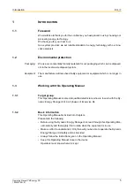
Page 5: ...or equipment which is no longer in use 1 3 Working with this Operating Manual 1 3 1 Target group This Operating Manual is aimed at qualified electricians who are to work with the Dy namic Energy Stora...

Page 6: ...Switch on the main switch The lamp illuminates Image items and relationship between text and image Important details are marked with numbers e g in diagrams This is referred to in the text by this num...

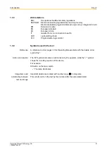
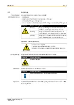
Page 7: ...plication Application stands for drive unit with frequency converter or servo drive in this Operating Manual Pictogram Signal word Danger Danger Danger with a high level of risk which can cause death...

Page 8: ...cations are met Expansion Module EM Expansion modules EM are connected to the Dynamic Energy Storage Unit to increase its energy storage capacity If several Dynamic Energy Storage Units are connected...

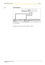
Page 9: ...Operating Manual PMCenergy SD 1004547 EN 01 Description of the device English 9 2 3 Type designation Fig 1 Type designation Description of the expansion module Chapter 7 page 27...

Page 10: ...g 2 OverviewDynamic Energy Storage Unit 1 Mounting holes 4x dia 6 5 2 Connecting terminals for extension module X1 3 Indicator LED 4 Label showing installation location 5 Type plate 6 Warnings 7 RS422...

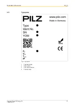
Page 11: ...Operating Manual PMCenergy SD 1004547 EN 01 Description of the device English 11 2 5 Type plate Fig 3 Type plate 1 Type designation 2 Serial number 3 Year of manufacture 4 Technical data...

Page 12: ...LED on the top While discharging the lamp should flash more slowly If in doubt measure the voltage between the DC link connecting terminals DC and DC at the bottom of the Dynamic Energy Storage Unit...

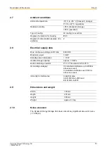
Page 13: ...ype of cooling Air cooling convection Degree of protection for housing IP20 Degree of contamination at place of in stallation 2 Max continuous voltage on DC link 800 VDC Maximum power 18 kW Standby po...

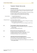
Page 14: ...must be done in an emergency Provide first aid to all injured persons Call a doctor or your in house paramedic Notify your manager Follow the instructions from your managers and first aid staff 3 2 Th...

Page 15: ...5 Requirements Underwriters Laboratories UL Only use 60 75 C copper stranded wire Marking for proper connection of the power supply the electrical load and its regulation For use in the following envi...

Page 16: ...g the delivery Check the packaging for damage Immediately notify the transport company about any damage to the packaging and or the Dynamic Energy Storage Unit The transport company must receive a wri...

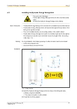
Page 17: ...e Unit needs to be installed right next to the applica tion frequency converter servo controller due to the length of the connecting cable max 1 m Spacing During installation the following spacings to...

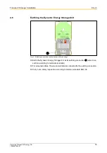
Page 18: ...e Unit Fig 5 Earthing connection on the bottom of the housing Earth the Dynamic Energy Storage Unit at its earthing connection wire cross section according to national standards For screened cables th...

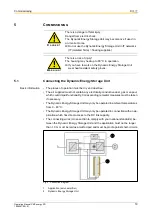
Page 19: ...cess to the DC link capacity The connecting wires cross section to comply with your national standards be tween the Dynamic Energy Storage Unit and the application must not be longer than 1 0 m must b...

Page 20: ...l and DC red terminal This procedure applies for automatic setting of the operating voltage on the DC link The brake resistor line is not connected in case for fixed setting of operating voltage on th...

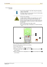
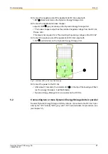
Page 21: ...ting voltage on the DC link Connect the positive pole of the application s DC link output with DC red terminal on the Dynamic Energy Storage Unit Fig 8 Indicator LED on the top of the housing Connect...

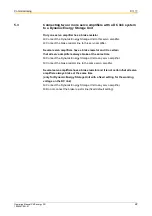
Page 22: ...e a brake resistor and it is certain that all servo amplifiers always brake at the same time Connect the Dynamic Energy Storage Unit to any servo amplifier Connect the brake resistor line to the same...

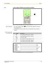
Page 23: ...Unit This interface must be connected with an external RS422 communications interface The pin assignments for connector X4 Fig 10 The pin assignments of connector X4 and the external interface Pin Si...

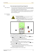
Page 24: ...c Energy Storage Unit plug in the discharge bridge between DC black terminal and BR grey terminal The Dynamic Energy Storage Unit will be discharged After the Dynamic Energy Storage Unit has been full...

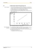
Page 25: ...on the model plate Page 11 Fig 3 During conditioning the Dynamic Energy Storage Unit is connected to the DC link but is not ready for use Fig 12 Conditioning time depending on the voltage free period...

Page 26: ...it can only be repaired by its manufacturer 6 4 Disposing of an Dynamic Energy Storage Unit Disconnect the Dynamic Energy Storage Unit Page 24 chap 5 5 Disconnect ing the Dynamic Energy Storage Unit R...

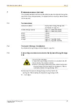
Page 27: ...rage Unit Disconnect the Dynamic Energy Storage Unit from the DC link Page 24 Disconnecting the Dynamic Energy Storage Unit next page Ambient conditions See Dynamic Energy Storage Unit Chapter 2 7 pag...

Page 28: ...upplied connecting cable into X2 and X3 and wait for approximately 30 seconds The extension module will be discharged Fig 14 Discharging the Dynamic Energy Storage Unit top side of the housing On the...

Page 29: ...h the connecting cable from X3 and insert it into X1 on the extension module The Dynamic Energy Storage Unit and the extension module are connected 7 4 Connecting an additional extension module Fig 16...

Page 30: ...nd wait for approx 30 seconds Extension module 1 will be discharged Fig 18 Connecting a Dynamic Energy Storage Unit and two extension modules On extension module 2 undo connector X3 and insert it into...

Page 31: ...ating Manual PMCenergy SD 1004547 EN 01 Ordering data English 31 8 ORDERING DATA Order No Product type Features 8176860 PMCenergy SD B2 Dynamic Energy Storage Unit 8176862 PMCenergy SD E1 Extension mo...

Page 32: ...tyBUS p SafetyEYE SafetyNET p THE SPIRIT OF SAFETY are registered and protected trademarks of Pilz GmbH Co KG in some countries We would point out that product features may vary from the details state...

Reviews: