
Operating Manual PMCenergy SD
1004547-EN-01
Commissioning
En
gl
is
h
25
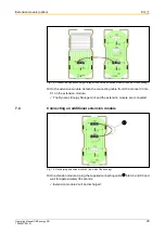
5.6
Conditioning the Dynamic Energy Storage Unit
Basic information
• If the Dynamic Energy Storage Unit has been de-energised for more than 1 year,
it must be conditioned. Failure to do this may result in the Dynamic Energy Storage
Unit being damaged when the main supply voltage is switched on.
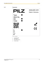
• The date of manufacture is on the model plate (
• During conditioning, the Dynamic Energy Storage Unit is connected to the DC link
but is not ready for use.
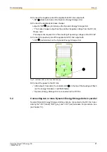
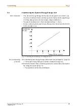
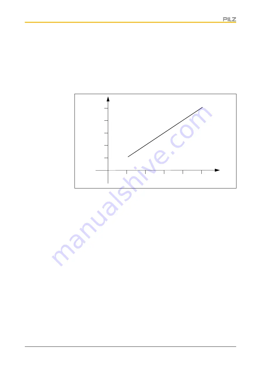
Fig. 12: Conditioning time, depending on the voltage-free period
The commissioning
procedure
⌧
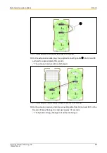
Connect the Dynamic Energy Storage Unit to the DC link (
The Dynamic Energy Storage Unit will be conditioned (charged up).
⌧
Wait for the duration of the conditioning period which corresponds to the length of
the voltage-free period (
The application can then be enabled again.
Voltage-free time [years]
Conditioning
5
4
3
2
1
1
2
3
4
5
time [h]


