Function description
Operating Manual PMCprimo MC
1003813-EN-03
| 17
4.1.2
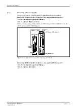
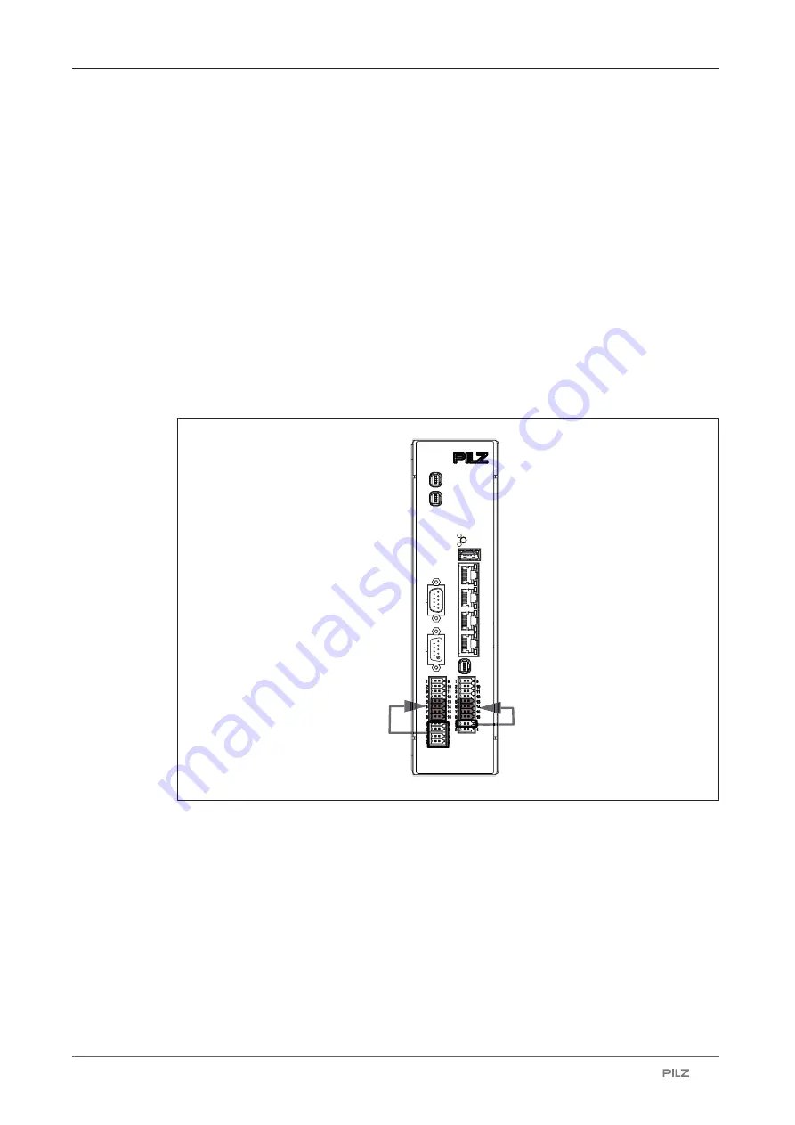
Connecting the supply voltage
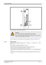
Connect the following supply voltages to the device:
Supply voltage
for the device, the digital outputs and interfaces
}
X40a/Pin 1 and Pin 3
Supply voltage for the device, the digital outputs X40b (24 VDC), the interfaces X42 to
X45 and the interfaces X51 and X52
}
X50a/Pin 1 and Pin 3 and X50b/Pin 1 and Pin 3
Supply voltage for the digital outputs X50c (24 V DC).
The following terminals are linked internally:
– X50a/Pin 1 and X50b/Pin 1 (24 V)
– X50a/Pin 3 and X50b/Pin 3 (0 V)
– X50a/Pin 2 and X50b/Pin 2
– X50a/Pin 4 and X50b/Pin 4
X46
USB
SNet
CAN1
X45
Out
X43
In
X44
SNet
RESET
ETH
FUNC
X41
ENC1
STAT
CAN2
X56
ENC2
X55
ENC3
X52
CAN3
X51
CAN4
X50c
X50b
X50a
PB
X40a
X40b
X42
X40a
X40a
X50ab
X40b
X50c
Fig.: Connecting the supply voltage for device, digital outputs and interfaces
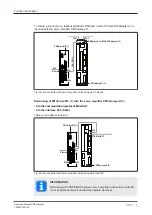
Connect the following supply voltages for the encoders:
}
X40a/Pin 2 and Pin 4
Supply voltage for the encoder X41 (5 V, 10-30 VDC).
The voltage is wired directly to the Mini-I/O socket X41/Pin 1 and Pin 2.
}
X50a/Pin 1 and Pin 3 and X50b/Pin 1 and Pin 3
Supply voltage for the two encoders X55 and X56 (5 V, 10-30 V DC).
The following terminals are linked internally:
- X50a/Pin 1 and X50b/Pin 1 (24 V)
- X50a/Pin 3 and X50b/Pin 3 (0 V)

