Operation
Operating Manual PMCprimo MC
1003813-EN-03
| 55
8
Operation
8.1
Operating states and changes in operating status
8.1.1
Status graph
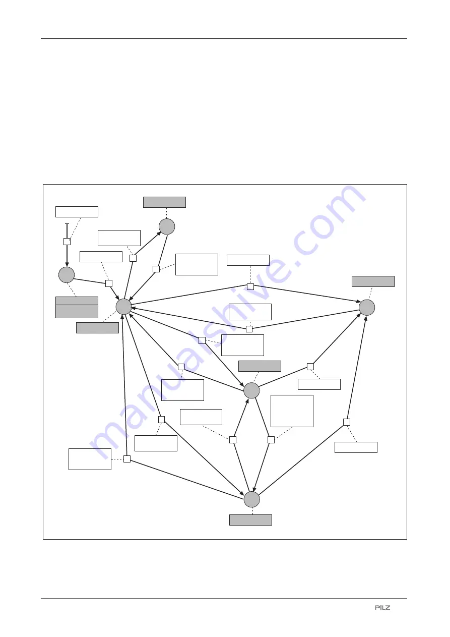
The following status graph shows the operating states and changes in operating status.
The priority of a transition is indicated by a number in a small square in the middle of the
transition arrow. The operating states and changes in operating status are described in de-
tail below.
1
1
3
4
5
2
Startup
0
1
Power Off
X40/7 = 0 V
RUN
X40/7 = 0 -> 24 V
Press reset
button
Boot Menu
Exit Boot
Menu
Command?
Fatal Error
Error detected
STOP
No user
program
HW reset:
- RS1
- Reset button
- RS3 or
reset button
- RS4
- RS5
- RS6
Automatic
HW reset
User
program
available
HW reset:
- RS1
- Reset button
X40/7 = 24 -> 0 V
2
1
1
3
2
1
Error detected
3
2
1
Error detected
2
2
RS2 or
reset button
1
1
Fig.: Operating states and changes in operating status of the motion controller

