Commissioning
Operating Manual PMD s10
22092-EN-05
| 27
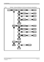
Default value
Parameters can be set from ... to
Leave unchanged
…
-> Rel. K1
Po Pu
…
-> Rel. K1
Escape
Rel. K2
Pu
-> Rel. K2
Pu
-> Rel. K2
Pwo
...
...
-> Rel. K2
Pwu
-> Rel. K2
Pwo Pwu
-> Rel. K2
Escape
Rel. K1
norm. on
-> Rel. K1
norm. on
-> Rel. K1
norm. off
-> Rel. K1
Escape
Rel. K2
norm. on
-> Rel. K2
norm. on
-> Rel. K2
norm. off
-> Rel. K2
Escape
ext. CT
1 : 1
-> ext. CT
1 : 1
-> ext. CT
1000 : 1
-> ext. CT
Escape
ext. VT
1 : 1
-> ext. VT
1 : 1
-> ext. VT
100 : 1
-> ext. VT
Escape
Load
Default
-> Load
Def. Esc
-> Load
Def. yes?
-> Default
Loaded
Adv. Set.
Escape
7.6
Procedure for setting parameters
NOTICE
Ensure that the parameters are set correctly for PMD s10. True power over-
load or underload can damage machinery or disrupt process cycles. Simu-
late load cases once the parameters have been set!
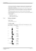
This section describes the main procedure for setting the parameters. In the following
pages, the procedure is described using real examples.
Setting the parameters:
}
If the unit PMD s10 is connected to a current transformer and/or a voltage transformer,
set the CT/VT transmission ratio (default setting: 1 : 1).
}
Set the load's maximum true power Pmax:
– Read the value on the type label or data sheet.
– or: Operate the motor at the highest permitted load; read the current value on the dis-
play and set the Pmax.
}
Set the switching threshold for overload Po.
}
Operate the motor in normal mode.


