- 1 -
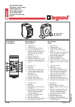
Das Sicherheitsschaltgerät PNOZ e6vp
Das Schaltgerät PNOZ e6vp dient dem
sicherheitsgerichteten Unterbrechen eines
Sicherheitsstromkreises. Das Gerät erfüllt
Forderungen der EN 954-1 oder
EN ISO 13849-1 bis Kategorie 4. Das PNOZ
e6vp hat einen integrierten Kontakt-
erweiterungsblock.
Das Gerät erfüllt Forderungen der EN 60947-
5-1, EN 60204-1 und VDE 0113-1 und darf
eingesetzt werden in Anwendungen mit
• Not-Halt-Schaltern
• Schutztüren
Wichtige Daten für Projektierung und
Anwendung finden Sie auch im technischen
Katalog PNOZelog.
Safety Relay PNOZ e6vp
The safety relay PNOZ e6vp is used for the
safety-related interruption of a safety circuit.
The unit meets EN 954-1 or EN ISO 13849-
1 requirements up to and including
Category 4. The PNOZ e6vp has an
itegrated contact extension block.
The unit meets requirements of EN 60947-5-
1, EN 60204-1 and VDE 0113-1 and can be
used in applications with
• Emergency stop buttons
• Safety gates
Important data for project planning and
application can also be found in the
PNOZelog technical catalogue.
21166-3FR-06
PNOZ e6vp
4
D
Betriebsanleitung
4
GB Operating instructions
4
F
Manuel d'utilisation
For your safety
The safety relay PNOZ e6vp meets all the
necessary conditions for safe operation.
However, please note the following safety
regulations:
• Only install and commission the unit if you
have read and understood these
instructions and are familiar with both
these instructions and the current
regulations for health and safety at work
and accident prevention.
• Only use the unit in accordance with its
intended purpose. Please also take note of
the values in the “Technical details”
section.
• Transport, storage and operating
conditions should all conform to the
standards as stated under “Technical
details”.
• Do not open the housing or undertake any
unauthorised modifications.
• Please make sure you shut down the
supply voltage, or open the input circuit
(e.g. operate the E-STOP button) when
performing maintenance work (e.g. when
replacing contactors). In case of a wiring
error, the device might switch on
unexpectedly.
You must take note of the warnings given in
other sections of these operating instructions.
These are highlighted visually through the
use of symbols.
Notice: Failure to keep to these safety
regulations will render all warranty
invalid.
Description
Safety features:
The relay fulfils the following safety
requirements:
• The circuit is redundant with built-in self-
monitoring.
• The safety function remains effective in the
case of a component failure.
• The safety outputs 14 and 24 are tested
periodically using a disconnection test.
• The unit has an electronic fuse.
Bloc logique de sécurité PNOZ e6vp
Le bloc logique de sécurité PNOZ e6vp
assure de façon sûre l'ouverture d'un circuit
de sécurité. Ce bloc logique satisfait aux
exigences de la norme EN 954-1,
EN ISO 13849-1 jusqu’à la catégorie 4. Le
PNOZ e6vp est équipé d'un bloc d'extension
de contacts intégré.
L'appareil satisfait aux exigences des normes
EN 60947-5-1, EN 60204-1 et VDE 0113-1 et
peut être utilisé dans les applications des
• poussoirs d'arrêt d'urgence
• protecteurs mobiles
Vous trouverez également des données
importantes pour la configuration projet et
l’utilisation dans le Catalogue technique
PNOZelog.
Pour votre sécurité
Le bloc logique de sécurité PNOZ e6vp
satisfait à toutes les conditions nécessaires
pour un fonctionnement sécuritaire.
Toutefois, vous êtes tenu de respecter les
prescriptions de sécurité suivantes :
• Vous n’installerez l’appareil et ne le
mettrez en service qu’après vous
être familiarisé avec le présent manuel
d’utilisation et les prescriptions en vigueur
sur la sécurité du travail et la prévention
des accidents.
• N'utilisez l'appareil que conformément à sa
définiton. A ce sujet, respectez les valeurs
indiquées dans les "Caractéristiques
techniques".
• Pour le transport, le stockage et
l'utilisation, respectez les exigences des
normes specifiées (voir „Caractéristiques
techniques“).
• N’ouvrez pas le boîtier et n'effectuez pas
de modifications non autorisées.
• En cas de travaux de maintenance (par
ex. remplacement des contacteurs) coupez
impérativement la tension d’alimentation ou
ouvrez le circuit d’entrée (action sur le BP
d’arrêt d’urgence), sinon un réarmement
inopiné du relais est possible en cas
d’erreur de câblage.
Respectez impérativement les avertissements
dans les autres paragraphes du présent
manuel d’utilisation. Ces avertissements sont
signalés par des symboles visuels.
Important : Respectez les consignes
de sécurité, sinon la garantie devient
caduque.
Description de l’appareil
Propriétés de sécurité :
Le bloc logique de sécurité satisfait aux
exigences de sécurité suivantes :
• Conception redondante avec auto-
surveillance.
• Fonction de sécurité garantie même en
cas de défaillance d'un composant interne
• Les sortie de sécurité 14 et 24 sont testées
périodiquement à l'aide d'un test de
coupure.
• L'appareil est équipé d'un fusible
électronique.
Zu Ihrer Sicherheit
Das Sicherheitsschaltgerät PNOZ e6vp
erfüllt alle notwendigen Bedingungen für
einen sicheren Betrieb.
Beachten Sie jedoch nachfolgend aufge-
führte Sicherheitsbestimmungen:
• Installieren und nehmen Sie das Gerät nur
dann in Betrieb, wenn Sie diese Betriebs-
anleitung gelesen und verstanden haben
und Sie mit den geltenden Vorschriften
über Arbeitssicherheit und Unfallverhü-
tung vertraut sind.
• Verwenden Sie das Gerät nur gemäß
seiner Bestimmung. Beachten Sie dazu
auch die Werte im Abschnitt “Technische
Daten”.
• Halten Sie beim Transport, bei der
Lagerung und im Betrieb die Bedingungen
ein, wie sie unter "Technische Daten"
angegeben sind.
• Öffnen Sie nicht das Gehäuse und
nehmen Sie auch keine eigenmächtigen
Umbauten vor.
• Schalten Sie bei Wartungsarbeiten (z. B.
beim Austausch von Schützen) unbedingt
die Versorgungsspannung ab oder öffnen
Sie den Eingangskreis (z. B. Not-Halt-
Taster betätigen), sonst kann das Gerät
bei Verdrahtungsfehlern unerwartet
einschalten.
Beachten Sie unbedingt die Warnhinweise in
den anderen Abschnitten dieser Anleitung.
Diese Hinweise sind optisch durch Symbole
hervorgehoben.
Wichtig: Beachten Sie die Sicher-
heitsbestimmungen, sonst erlischt
jegliche Gewährleistung.
Gerätebeschreibung
Sicherheitseigenschaften:
Das Schaltgerät erfüllt folgende Sicher-
heitsanforderungen:
• Die Schaltung ist redundant mit Selbst-
überwachung aufgebaut.
• Die Sicherheitseinrichtung bleibt auch bei
Ausfall eines Bauteils wirksam.
• Die Sicherheitsausgänge 14 und 24
werden durch einen Abschalttest peri-
odisch geprüft.
• Das Gerät besitzt eine elektronische
Sicherung.


