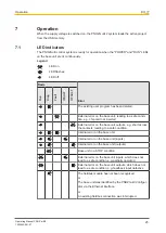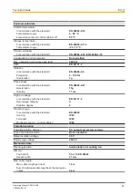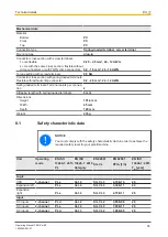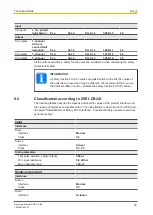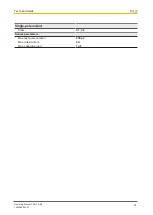
Operation
Operating Manual PNOZ m B0
1002660-EN-07
30
7.2.3
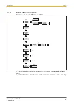
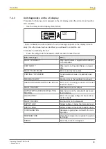
Unit diagnostics on the LC display
Procedure for showing error messages on the LC display, when the errors do not lead to a
safe condition:
}
Use the rotary knob to display stored errors:
Output
faulty
*
X3
X1
X2
X4
T T
M
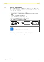
* If an error leads to a safe condition, the error message appears on the display immedi-
ately. Once the cause has been rectified, you will need to restart the unit
Procedure for restarting the unit:
}
Press the rotary knob for between 3 and 8 seconds to reset the unit.
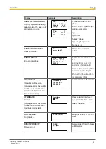
Error messages
Error
FAULTY PROJECT
Chip card contains a project which is faulty
or incompatible.
CHIP CARD ?
Chip card is not inserted, blank or unread-
able
FAULTY TEST PULSE
Error caused by test pulses
PARTIALLY OPERATED
Function element was or is partially oper-
ated
FEED BACK LOOP
Exernal error at the feedback loop inputs
OPERATING MODE SWITCH SELECTOR
Error on the operating mode selector switch
function element
FAULTY OUTPUT
External error on the output
OUTPUT WITH ADVANCED FAULT DE-
TECTION
External error on the output with advanced
fault detection
LOAD SUPPLY
Error in the supply voltage for the semicon-
ductor outputs
FAULTY DEVICE
Internal error on the base unit
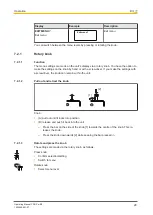
SUPPLY LOW
Supply voltage is below the tolerance level
SUPPLY HIGH
Supply voltage exceeds the tolerance level
CONFIGURATION
Hardware registry does not match the con-
figuration
TEMPERATURE
Operating temperature is outside the permit-
ted range
ERROR
Error that cannot be assigned

