PNOZ m ES Profibus
Operating Manual PNOZ m ES Profibus
1002698EN04
11
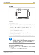
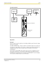
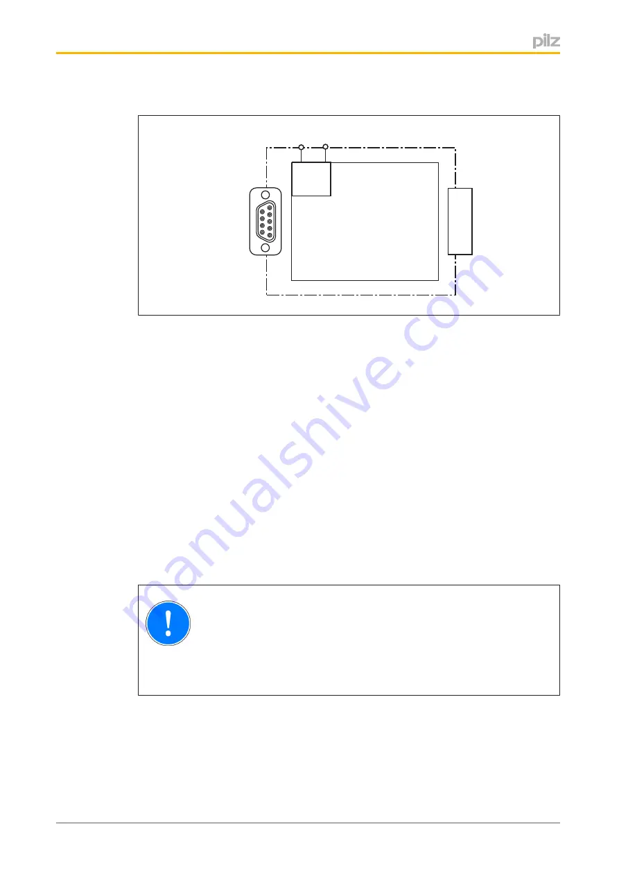
Block diagram
Base unit
PROFIBUS DP
24 V 0 V
24 V 0 V
Installation
General installation guidelines
}
The unit should be installed in a single mounting area with a protection type of at least
IP54.
}
Fit the safety system to a horizontal mounting rail. The venting slots must face upwards
and downwards. Other mounting positions could destroy the safety system.
}
Use the locking slide on the rear of the unit to attach it to a mounting rail.
}
In environments exposed to heavy vibration, the unit should be secured using a fixing
element (e.g. retaining bracket or end angle).
}
Open the locking slide before lifting the unit from the mounting rail.
}
To comply with EMC requirements, the mounting rail must have a low impedance con
nection to the control cabinet housing.
}
The ambient temperature of the PNOZmulti units in the control cabinet must not exceed
the figure stated in the technical details, otherwise air conditioning will be required.
NOTICE
Damage due to electrostatic discharge!
Electrostatic discharge can damage components. Ensure against discharge
before touching the product, e.g. by touching an earthed, conductive sur
face or by wearing an earthed armband.
Connect the base unit and expansion modules
Connect the base unit and the expansion module as described in the operating instructions
for the base units.
}
Connect the black/yellow terminator to the expansion module.

