PNOZ m ES Profibus
Operating Manual PNOZ m ES Profibus
1002698EN04
12
}
Install the expansion module in the position in which it is configured in the PNOZmulti
Configurator.
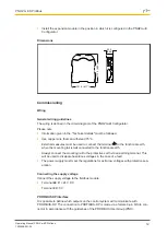
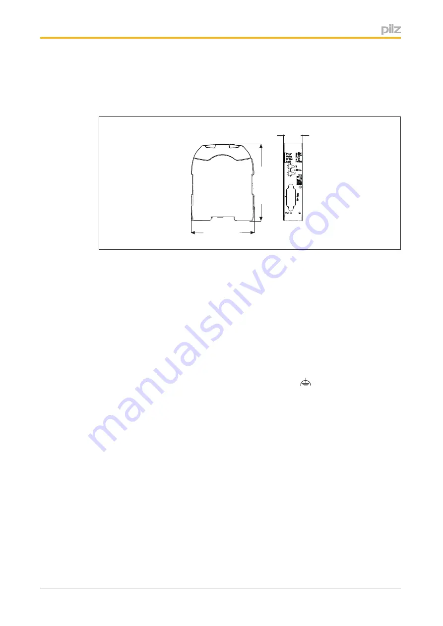
Dimensions
101,4 (4,11
“
)
1
1
5
,0
(4
,5
3
“
)
22,5
(0,88“)
Commissioning
Wiring
General wiring guidelines
The wiring is defined in the circuit diagram of the PNOZmulti Configurator.
Please note:
}
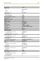
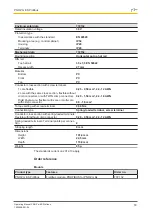
Information given in the "Technical details" must be followed.
}
Use copper wire that can withstand 75°C.
}
External measures must be used to connect the terminal
to the functional earth,
when the mounting rail is
not
connected to the functional earth.
}
Always connect the mounting rail to the protective earth via an earthing terminal. This
will be used to dissipate hazardous voltages in the case of a fault.
}
The power supply must meet the regulations for extra low voltages with protective sep
aration.
Connecting the supply voltage
Connect the supply voltage to the fieldbus module:
}
Terminal
24 V
: + 24 V DC
}
Terminal
0 V
: 0 V
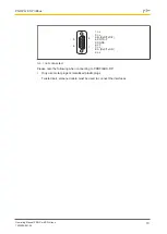
PROFIBUS DP interface
It is possible to define which outputs on the control system will communicate with
PROFIBUSDP. The connection to PROFIBUSDP is made via a female 9pin DSub con
nector in accordance with the guidelines of the PROFIBUS User Group (PNO).

