background image

Operating Manual — No. 1002053-EN-03

PNOZmulti Modular Safety System

PNOZ m0p

_Name_Bookmark2_

_Name_Bookmark2_

Summary of Contents for PNOZ m0p

Page 1: ...Operating Manual No 1002053 EN 03 PNOZmulti Modular Safety System PNOZ m0p _Name_Bookmark2_ _Name_Bookmark2_...

Page 2: ...ay be made for internal purposes Suggestions and comments for improving this documentation will be gratefully received Pilz PIT PMI PNOZ Primo PSEN PSS PVIS SafetyBUS p SafetyEYE SafetyNET p the spiri...

Page 3: ...OZ m0p 2 3 2 2 2 PNOZ m0p ETH 2 3 2 2 3 Key 2 4 Chapter 3 Safety 3 1 Intended use 3 1 3 1 1 System requirements 3 1 3 2 Safety regulations 3 2 3 2 1 Use of qualified personnel 3 2 3 2 2 Warranty and l...

Page 4: ...y sys tem for the first time 6 5 6 3 2 1 Load project from chip card 6 5 6 3 2 2 Load project via integrated interface 6 6 6 3 3 Download modified project to the PNOZmulti safety system 6 6 6 3 3 1 Lo...

Page 5: ...entation 1 Einf Gltigkeit der Dokumentation This documentation is valid for the product PNOZ m0p It is valid until new documentation is published Einf Einleitung This operating manual explains the fun...

Page 6: ...of this manual 2 Overview This chapter provides information on the product s most important fea tures 3 Safety This chapter must be read as it contains important information on in tended use 4 Functio...

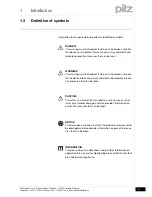
Page 7: ...that can be taken WARNING This warning must be heeded It warns of a hazardous situation that could lead to serious injury and death and indicates preven tive measures that can be taken CAUTION This r...

Page 8: ...1 Introduction Pilz GmbH Co KG Felix Wankel Stra e 2 73760 Ostfildern Germany Telephone 49 711 3409 0 Telefax 49 711 3409 133 E Mail pilz gmbh pilz de 1 4...

Page 9: ...le PNOZ m0p Can be configured in the PNOZmulti Configurator Positive guided relay outputs 2 safety outputs Depending on the application up to PL e of EN ISO 13849 1 and up to SIL CL 3 of EN IEC 62061...

Page 10: ...the inputs through test pulse outputs Monitoring of shorts between the safety outputs Plug in connection terminals either cage clamp terminal or screw ter minal 2 1 3 Chip card Chip card 2 Bestimmung...

Page 11: ...49 711 3409 133 E Mail pilz gmbh pilz de 2 3 2 2 Front view 2 Overview 2 2 Front view 2200 Front view 2 2 2 1 PNOZ m0p PNOZ m0p 2 Z PNOZmulti Basis RS232 front x EPS 2 2 2 PNOZ m0p ETH PNOZ m0p ETH 2...

Page 12: ...Key Key 2 Legende_Klemmenbelegung_multi_Basis_ETH RS232_BA Key CHIP card Interface chip card X1 Cascading inputs and outputs CI and CO Test pulse outputs T0 T3 X2 Semiconductor outputs O0 O3 Auxiliary...

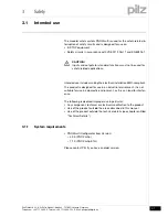
Page 13: ...schluss Intended use includes making the electrical installation EMC compliant The product is designed for use in an industrial environment It is not suitable for use in a domestic environment as this...

Page 14: ...Are familiar with the basic regulations concerning health and safety accident prevention Have read and understood the safety guidelines given in this descrip tion Have a good knowledge of the generic...

Page 15: ...ual only describes the basic functions of the unit Information on the expanded functions such as cascading can be found in the online help for the PNOZmulti Configurator and in the PNOZmulti technical...

Page 16: ...3 Safety Pilz GmbH Co KG Felix Wankel Stra e 2 73760 Ostfildern Germany Telephone 49 711 3409 0 Telefax 49 711 3409 133 E Mail pilz gmbh pilz de 3 4...

Page 17: ...her circuits in the safety sys tem Sicherheitseigenschaften_Halbleiter The safety outputs are tested periodically using a disconnection test 4 1 2 Function description Function description 4 4 1 2 1 O...

Page 18: ...possible via the interfaces or one of the fieldbus modules e g the PROFIBUS module 4 1 2 4 Cascading Cascading 4 Funktionen_multi_Basis_Kaskadierung The cascading inputs and outputs enable several PN...

Page 19: ...ad the project Read the diagnostic data Set virtual inputs for standard functions Read virtual outputs for standard functions Information on diagnostics via the interfaces can be found in the Special...

Page 20: ...4 Function description Pilz GmbH Co KG Felix Wankel Stra e 2 73760 Ostfildern Germany Telephone 49 711 3409 0 Telefax 49 711 3409 133 E Mail pilz gmbh pilz de 4 4...

Page 21: ...ystem Use the notches on the back of the unit to attach it to a DIN rail Con nect the safety system to the DIN rail in an upright position so that the earthing springs on the safety system are pressed...

Page 22: ...elines 5 Installation Pilz GmbH Co KG Felix Wankel Stra e 2 73760 Ostfildern Germany Telephone 49 711 3409 0 Telefax 49 711 3409 133 E Mail pilz gmbh pilz de 5 2 5 1 1 Dimensions Dimensions 5 Abmessun...

Page 23: ...5200 Connecting the base unit and expansion modules 5 Montage_multi_Basis_verbind_mit_Modul_links PNOZ m0p_BA Jumpers are used to connect the modules There are 2 pin connectors on the rear of the base...

Page 24: ...5 Installation Pilz GmbH Co KG Felix Wankel Stra e 2 73760 Ostfildern Germany Telephone 49 711 3409 0 Telefax 49 711 3409 133 E Mail pilz gmbh pilz de 5 4...

Page 25: ...must be provided on all output contacts with inductive loads Power for the safety system and input circuits must always be provid ed from a single power supply The power supply must meet the reg ulati...

Page 26: ...and crossover cable crossover data line connec tion The switch automatically creates the correct data line connection internally It is therefore possible to use patch cable as the connection cable for...

Page 27: ...nal autosensing switch enable process data to be exchanged with other Ethernet subscribers within a network The product PNOZ m0pETH can also be connected to Ethernet via a hub hub or switch ETH_Prozes...

Page 28: ...ephone 49 711 3409 0 Telefax 49 711 3409 133 E Mail pilz gmbh pilz de 6 4 Fig 6 1 PNOZmulti as Ethernet subscriber possible topologies Ethernet Hub Switch Hub Switch Ethernet subscriber Ethernet subsc...

Page 29: ...ply voltage for the units connector X7 Terminal A1 24 VDC Terminal A2 0 V Supply voltage for the semiconductor outputs connector X2 Terminal 24 V 24 VDC 0V terminal 0 V Note Supply voltage must always...

Page 30: ...oject from chip card 6 Verdrahtung_multi_Basis_Betr_geaend_Projekt_von_Chipkarte_BA To download data via chip card the existing configuration data must first be deleted general reset of device Procedu...

Page 31: ...circuit Supply voltage AC DC For the safety system connector X7 For the semiconductor outputs connector X2 Must always be present even if the semiconductor outputs are not used Input circuit Single c...

Page 32: ...nection examples for semiconductor outputs Connection examples for relay outputs Connection examples for feedback loop Redundant output Single output Redundant output Single output Feedback loop Redun...

Page 33: ...6 4 Connection example 6400 Connection example 6 Anschlussbeispiel_Basisger te_BA Dual channel E STOP and safety gate wiring monitored reset I17 feedback loop I14 cascading output as auxiliary output...

Page 34: ...6 Commissioning Pilz GmbH Co KG Felix Wankel Stra e 2 73760 Ostfildern Germany Telephone 49 711 3409 0 Telefax 49 711 3409 133 E Mail pilz gmbh pilz de 6 10...

Page 35: ...se unit leading to a safe condition e g terminator not connected External error leading to a safe condition e g short across the contacts or error on safety mat input External error on the outputs of...

Page 36: ..._fuer_Ethernet_LNK_TRF The operating statuses and fault conditions of the Ethernet connection are shown via the LEDs LNK link and TRF traffic at the Ethernet inter faces The fieldbus module has not be...

Page 37: ...t connection settings 7 ETH_Verbindungseinstellungen_zuruecksetzen_multi The Ethernet connection settings of the base unit can be configured in the PNOZmulti Configurator You can reset the base unit s...

Page 38: ...7 Operation Pilz GmbH Co KG Felix Wankel Stra e 2 73760 Ostfildern Germany Telephone 49 711 3409 0 Telefax 49 711 3409 133 E Mail pilz gmbh pilz de 7 4...

Page 39: ...Number 20 Max number of live inputs in the area of max permitted ambient temperature see Environmental data U_B 26 4 V 15 U_B 26 4 V 20 Voltage and current at input reset and feedback circuit 24 0 V 8...

Page 40: ...6 A Circuit breaker 24 VAC DC characteristic B C 6 A Switch off delay 50 ms Auxiliary outputs Number 1 Switching capability voltage 24 V current 0 5 A power 12 0 W Galvanic isolation yes Short circui...

Page 41: ...insulating sleeve 0 50 1 25 mm 22 16 AWG without crimp connectors or with TWIN crimp connectors 0 50 1 25 mm 22 16 AWG Torque setting with screw terminals 0 25 Nm Cross section of external conductors...

Page 42: ...stic data Technische Daten_Satz Normen The standards current on 2009 03 apply Si Kennzahlen_Zusatz_Relais_Lebensdauer_BA The PFH value depends on the switching frequency and the load on the relay outp...

Page 43: ...Provided the application requires fewer than 1 000 000 cycles the PFH value see technical details can be used in the calculation To increase the service life sufficient spark suppression must be provi...

Page 44: ...tfildern Germany Telephone 49 711 3409 0 Telefax 49 711 3409 133 E Mail pilz gmbh pilz de 8 6 8 3 Maximum capacitive load C F with load current I mA at the semiconductor outputs 8300 Maximum capacitiv...

Page 45: ...ephone 49 711 3409 0 Telefax 49 711 3409 133 E Mail pilz gmbh pilz de 8 7 8 4 Order reference 8 Technical details 8 4 Order reference 8400 Order reference 8 Bestelldaten Order reference Type Features...

Page 46: ...8 Technical details Pilz GmbH Co KG Felix Wankel Stra e 2 73760 Ostfildern Germany Telephone 49 711 3409 0 Telefax 49 711 3409 133 E Mail pilz gmbh pilz de 8 8...

Page 47: ...etails or contact our headquarters InduraNET p Pilz PIT PMCprotego PMI PNOZ Primo PSEN PSS PVIS SafetyBUS p SafetyEYE SafetyNET p the spirit of safety are registered and protected trademarks of Pilz G...

Reviews: