Pilz GmbH & Co. KG, Felix-Wankel-Straße 2, 73760 Ostfildern, Germany
Telephone: +49 711 3409-0, Telefax: +49 711 3409-133, E-Mail: pilz.gmbh@pilz.de
6-1
6.1
General wiring guidelines
6
Commissioning
6
6000
Commissioning
Commissioning
6-
6.1
General wiring guidelines
6100
General wiring guidelines
6-
Verdrahtung_multi_Basis
The wiring is defined in the circuit diagram in the Configurator. There you
can select the inputs that are to perform a particular safety function and
the outputs that will switch this safety function.
Please note:
`
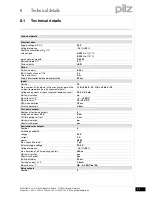
Information given in the “Technical details” must be followed.
`
Outputs:
– O0 to O5 are safety outputs
– O4 and O5 are relay outputs
– O0 to O3 are semiconductor outputs
– OA0 is an auxiliary output.
`
To prevent contact welding, a fuse should be connected before the
output contacts (see technical details).
`
Use copper wire that can withstand 75 °C.
`
Sufficient fuse protection must be provided on all output contacts
with inductive loads.
`
Power for the safety system and input circuits must always be provid-
ed from a single power supply. The power supply must meet the reg-
ulations for extra low voltages with safe separation.
`
Two connection terminals are available for each of the supply con-
nections 24 V and 0 V (semiconductor outputs), plus A1 and A2 (pow-
er supply). This means that the supply voltage can be looped through
several connections. The current at each terminal may not exceed 3
A.
`
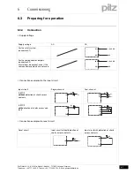
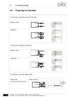
Test pulse outputs must exclusively be used to test the inputs. They
must not be used to drive loads.
Do not route the test pulse lines together with actuator cables within
an unprotected multicore cable.
Verdrahtung_multi_Basis_Schaltmatte
`
Test pulse outputs are also used to supply safety mats that trigger a
short circuit.
Test pulses that are used for the safety mat may not be reused for
other purposes.
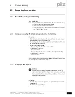
CAUTION!
DThe plug-in connection terminals on the relay outputs that
carry mains voltage should only be connected and disconnected
when the voltage is switched off.


