- 2 -
Modulbeschreibung
Sicherheitseigenschaften:
Das Erweiterungsmodul
PNOZ ml1p
erfüllt
folgende Sicherheitsanforderungen:
• Die Schaltung ist redundant mit Selbst-
überwachung aufgebaut.
• Die Sicherheitseinrichtung bleibt auch bei
Ausfall eines Bauteils wirksam.
Modulmerkmale:
• konfigurierbar im PNOZmulti Configurator
• sichere Punkt-zu-Punkt-Verbindung über
4adrige abgeschirmte Leitung, paarweise
verdrillt
• 32 virtuelle Eingänge und 32 virtuelle
Ausgänge
• Statusanzeigen
• steckbare Anschlussklemmen (wahlweise
Federkraftklemme oder Schraubklemme)
• Max. 4 PNOZ mlp an das Basisgerät
anschließbar
Funktionsbeschreibung
Arbeitsweise:
Das Verbindungsmodul PNOZ mlp dient
zur sicheren Übertragung von 32 virtuellen
Eingängen und 32 virtuellen Ausgängen
zwischen zwei PNOZmulti-Systemen.
Jedem Basisgerät ist ein Verbindungsmodul
zugeordnet. Der Datenaustausch erfolgt
zyklisch.
Die Funktionsweise der Ein- und Ausgänge
des Sicherheitssystems hängt von
der mit dem PNOZmulti Configurator
erstellten Sicherheitsschaltung ab. Die
Sicherheitsschaltung wird mittels Chipkarte
in das Basisgerät übertragen.
Das Basisgerät hat 2 Micro-Controller, die
sich gegenseitig überwachen. Sie werten
die Eingangskreise des Basisgeräts und
der Erweiterungsmodule aus und schalten
abhängig davon die Ausgänge des
Basisgeräts und der Erweiterungsmodule.
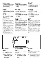
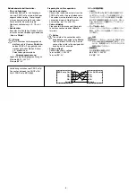
Fig. : Innenschaltbild
Fig. : Internal wiring diagram
図
:
内部配線図
����� ���
�
�����
�
�������
��������� ������� �������
��������� �����
������
�������
�������� ������� ������
Funktionen:
Die LEDs an Basisgerät und
Erweiterungsmodulen zeigen den Status des
Sicherheitssystems PNOZmulti an.
Info:
In der Online-Hilfe des
PNOZmulti Configurators finden
Sie Beschreibungen über die
Betriebsarten und alle Funktionen des
Sicherheitssystems PNOZmulti sowie
Anschlussbeispiele.
モジュールの概要
安全上の特徴
:
PNOZ ml1p
セーフティリンクモジュールは、
次の安全要件を満たしています。
•
自己監視機能が内蔵された冗長回路
•
安全機能は、部品故障の場合でも有効
モジュールの特徴
:
• PNOZmulti
コンフィグレータでコンフィグ
レーション可能
•
安全なポイントツーポイント接続
(4
芯のシールドツイストペアケーブルを使用
)
• 32
点の仮想入力と
32
点の仮想出力
•
ステータス表示
•
プラグイン接続端子
(
ケージ式端子または
スクリュー式端子
)
•
最大
4
台の
PNOZ mlp
ユニットをベース
ユニットに接続可能
機能の概要
動作
:
PNOZ mlp
セーフティリンクモジュールは、
2
台の
PNOZmulti
システム間で
32
点の仮想入
力および
32
点の仮想出力を安全に伝送するため
に使用します。セーフティリンクモジュールを
ベースユニットにそれぞれ
台ずつ接続します。
データ交換は周期的に行われます。
安全コントローラの入出力の機能は、
PNOZmulti
コンフィグレータを使用して作成した安全回路に
よって異なります。安全回路をベースユニットに
ダウンロードするには、チップカードを使用し
ます。
ベースユニットには
2
個のマイクロコントローラ
が搭載されており、相互に監視を行っています。
この
2
個のコントローラによってベースユニット
およびセーフティリンクモジュールの入力回路が
評価され、状況に応じてベースユニットおよび
セーフティリンクモジュールの出力が切り替わり
ます。
機能
:
ベースユニットおよびセーフティリンクモジュー
ルでは、
LED
によって
PNOZmulti
安全コント
ローラのステータスが示されます。
インフォメーション
:
PNOZmulti
コンフィグレータのオンラインヘルプで、
PNOZmulti
安全コントローラのオペレー
ティングモードとすべての機能に関する
説明、および接続例を参照できます。
Module description
Safety features:
The
PNOZ ml1p
expansion module fulfils the
following safety requirements:
• The circuit is redundant with built-in self-
monitoring.
• The safety function remains effective in the
case of a component failure.
Module features:
• Can be configured in the PNOZmulti
Configurator
• Secure point-to-point connection via
4-core shielded and twisted-pair cable
• 32 virtual inputs and 32 virtual outputs
• Status indicators
• Plug-in connection terminals (either spring-
loaded terminal or screw terminal)
• Max. 4 PNOZ mlp units can be connected
to the base unit
Function description
Operation:
The PNOZ mlp connection module is used
for the safe transfer of 32 virtual inputs and
32 virtual outputs between two PNOZmulti
systems. One connection module is assigned
to each base unit. Data is exchanged
cyclically.
The function of the inputs and outputs on the
safety system depends on the safety circuit
created using the PNOZmulti Configurator.
A chip card is used to download the safety
circuit to the base unit.
The base unit has 2 microcontrollers that
monitor each other. They evaluate the input
circuits on the base unit and expansion
modules and switch the outputs on the base
unit and expansion modules accordingly.
Functions:
The LEDs on the base unit and expansion
modules indicate the status of the PNOZmulti
safety system.
Information:
The online help on the
PNOZmulti Configurator contains
descriptions of the operating modes
and all the functions of the PNOZmulti
safety system, plus connection
examples.
Summary of Contents for PNOZ ml1p
Page 9: ...Notizen Notes...
Page 11: ...11...

