Operation
Operating Manual PNOZ mm0.1p
1002101-EN-04
24
7.2
Display indicators
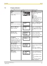
The LC display has four lines. It displays information and navigates the menu:
Display
Example
Description
RUN
State of inputs/outputs and
supply voltage
X3
X1
X2
X4
T T
M
The lines are assigned ter-
minals X1 ... X4
Status:
Semiconductor output active
Semiconductor output inactive
Test pulse output
Message display (bottom right):
Message present
Error message present
Input active
Input inactive
ERROR
Status and error messages
Feedback
loop
Line 1 ... 4: Status and error
messages as short text.
DISPLAY MESSAGE
Display messages
E-STOP
pressed
Line 1 ... 4: Customised
messages that are created
in the PNOZmulti Configur-
ator.
PROJECT INFO
Project information
PNOZ mm0p
project
CRC: 0x8108
09.02.2009
1st line: Project name
2nd line: Project name
3rd line: Check sum (CRC)
4th line: Creation date
IP ADDRESS
IP address of base unit
(only appears on base units
to which a communication
module with Ethernet inter-
face is connected)
IP Address
169.254.60.1/16
2nd line: IP address
INT. SAFE LINK
Internal interface for connec-
tion of two base units
(only appears on devices
with an integrated interface
for connection of two base
units)
Int. Safe Link
connected: yes
cable length:
max. 100 m
1st line: Name of interface
2nd line: Interface connected
yes/no
3rd-4th line: Configured
cable length (100 m/1000 m)
DEVICE INFO
Unit information
H 00000000003
HW 0x007
SW 0x0000
SN 0x000000009
1st line: Operating hours
since initial commissioning
(H)
2nd line: Software version
(SW)
3rd line: Hardware version
(HW)
4th line: Serial number of
PNOZ mm0p (SN)


