background image

Overview

Operating Manual PNOZ mmc6p
1002425-EN-03

7

2

Overview

2.1

Scope of supply

}

Expansion module PNOZ mmc6p

}

Jumper

2.2

Unit features

Using the product PNOZ mmc6p:
Expansion module for connection to a base unit from the configurable control system
PNOZmulti Mini
The product has the following features:

}

Can be configured in the PNOZmulti Configurator

}

Connection for CANopen

}

Station addresses from 0 ... 99, selected via rotary switch

}

Transmission rate selected via rotary switch (1 MBit/s, 10 kbit/s, 125 kBit/s, 20 kbit/s,
250 kBit/s, 50 kbit/s, 500 kBit/s, 800 kbit/s)

}

Status indicators for communication with CANopen and for errors

}

24 virtual inputs and outputs on the control system PNOZmulti can be defined in the
PNOZmulti Configurator for communication with the fieldbus CANopen . The number of
inputs and outputs can be extended to 128. Please note that when the extended inputs
and outputs 24 - 127 are used they have different properties (see document entitled
"Communication Interfaces").

}

Max. 1 PNOZ mmc6p can be connected to the base unit

}

Plug-in connection terminals:
either spring-loaded terminal or screw terminal available as an accessory (see order
reference)

}

For details of the PNOZmulti Mini base units that can be connected, please refer to the
document "PNOZmulti System Expansion".

Summary of Contents for PNOZ mmc6p

Page 1: ...PNOZ mmc6p Operating Manual 1002425 EN 03 Configurable compact control systems PNOZmulti Mini...

Page 2: ...umentation will be gratefully received Source code from third party manufacturers or open source software has been used for some components The relevant licence information is available on the Interne...

Page 3: ...escription 11 4 1 Operation 11 4 2 Input and output data 11 4 3 Assigning the inputs outputs in the PNOZmulti Configurator to the CAN open inputs outputs 11 4 4 Block diagram 12 Section 5 Installation...

Page 4: ...Contents Operating Manual PNOZ mmc6p 1002425 EN 03 4 Section 8 Technical details 20 Section 9 Order reference 22 9 1 Product 22 9 2 Accessories 22...

Page 5: ...is particularly important is identified as follows DANGER This warning must be heeded It warns of a hazardous situation that poses an immediate threat of serious injury and death and indicates prevent...

Page 6: ...Introduction Operating Manual PNOZ mmc6p 1002425 EN 03 6 INFORMATION This gives advice on applications and provides information on special fea tures...

Page 7: ...00 kBit s 800 kbit s Status indicators for communication with CANopen and for errors 24 virtual inputs and outputs on the control system PNOZmulti can be defined in the PNOZmulti Configurator for comm...

Page 8: ...Overview Operating Manual PNOZ mmc6p 1002425 EN 03 8 2 3 Front view Legend X4 0 V 24 V Supply connections X1 CANopen interface male 9 pin D Sub connector Functional earth LED Power Run Error...

Page 9: ...onnected refer to the document PNOZmulti System Expansion The configurable small control systems PNOZmulti are used for the safety related interrup tion of safety circuits and are designed for use in...

Page 10: ...d liability All claims to warranty and liability will be rendered invalid if The product was used contrary to the purpose for which it is intended Damage can be attributed to not having followed the g...

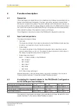
Page 11: ...of byte 1 has the number i12 Output range The outputs are defined in the PNOZmulti Configurator Each output that is used is given a number there e g o0 o5 The status of output o0 is stored in bit 0 of...

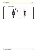
Page 12: ...Function description Operating Manual PNOZ mmc6p 1002425 EN 03 12 4 4 Block diagram Base unit CANopen 24V 0V 24V 0V...

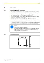
Page 13: ...secured using a fixing element e g retaining bracket or end angle Push the unit upwards or downwards before lifting it from the mounting rail To comply with EMC requirements the mounting rail must hav...

Page 14: ...o the expansion module Install the expansion module in the position in which it is configured in the PNOZmulti Configurator The position of the expansion modules is defined in the PNOZmulti Configurat...

Page 15: ...ail to the protective earth via an earthing terminal This will be used to dissipate hazardous voltages in the case of a fault The power supply must meet the regulations for extra low voltages with pro...

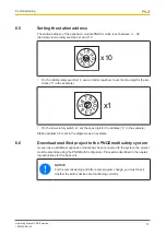
Page 16: ...used to connect the interfaces 6 3 1 CANopen termination To minimise cable reflection and to guarantee a defined rest signal on the transmission line CANopen must be terminated at both ends 6 4 Setti...

Page 17: ...4 9 8 7 6 0 5 x1 On the lower rotary switch x1 set the ones digit for the address 6 in the example Station address 36 is set in the diagrams as an example 6 6 Download modified project to the PNOZmul...

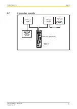
Page 18: ...Commissioning Operating Manual PNOZ mmc6p 1002425 EN 03 18 6 7 Connection example CANopen Master CANopen Slave 1 CANopen Slave 2 CANopen Slave 3 CANopen Slave n PNOZ mmc6p CANopen...

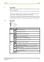
Page 19: ...and RUN status is displayed on CANopen The error message External Error is sent to the Master 7 1 Messages Legend LED on LED flashes LED off LED Key PWR Supply voltage is present Supply voltage is not...

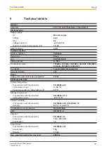
Page 20: ...nector Galvanic isolation yes Times Supply interruption before de energisation 20 ms Environmental data Ambient temperature In accordance with the standard EN 60068 2 14 Temperature range 0 60 C Force...

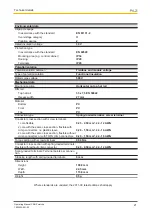
Page 21: ...mm Material Bottom PC Front PC Top PC Connection type Spring loaded terminal screw terminal Conductor cross section with screw terminals 1 core flexible 0 25 2 50 mm 24 12 AWG 2 core with the same cro...

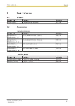
Page 22: ...Spring terminals PNOZ mmcxp 1 pc Spring loaded terminals 1 pieces 783 542 Spring terminals PNOZ mmcxp 10 pcs Spring loaded terminals 10 pieces 783 543 Screw terminals PNOZ mmcxp 1 pc Screw terminals 1...

Page 23: ...p ThE SPIrIT Of SAfETY are registered and protected trademarks of Pilz Gmbh Co KG in some countries We would point out that product features may vary from the details stated in this document dependin...

Reviews: